Combination type fan leaves structure

Inactive Publication Date: 2006-05-04
POWER COOLER ENTERPRISE
View PDF2 Cites 0 Cited by
  • Summary
  • Abstract
  • Description
  • Claims
  • Application Information

AI Technical Summary

Benefits of technology

[0009] A combination type fan leaves structure according to the present invention is a structure that separate molds are used for respectively fabricating the upper and the lower fan leaves components with a larger interval between two adjacent leaves on each component, and the upper and lower leaves components are then combined into a fan leaves body with a larger density of leaves by interlacing the leaves respectively disposed on them. Besides, because the interval between two adjacent leaves on each leaves component is larger, when the release of molds is process, even if the core and cavity molds need not be rotated, the release can be processed successfully. In addition, because the angle of release need not be taken into consideration when the molds are fabricated, a parting line can be designed not to appear on each leaf so that the work flow of the modification of the surfaces of the leaves and further to lower the production cost.
[0015] The fan leaves according to the present invention, a metal supporting frame can further be installed at the inner edge of the central frame of the fan leaves after assembling, a stronger supporting force is provided on the fan leaves components through the strong characteristic of the metal supporting frame structure to allow the upper fan leave structure and the lower fan leaves of the fan leaves structure according to the present invention to be combined tightly and stably into one body.

Problems solved by technology

But, that the temperature of the electronic element is too high owing to the increase of power consumption so that the electronic element is overheat, work abnormally or is even damaged.
Therefore, more procedures must be added in the manufacturing process and the production time and cost are further increased.
Besides, because when such kind of cooling face with rather densely arranged leaves is fabricated through stamping, because it is made by pressing the core mold 1b1 and cavity mold 1b2 together and the release angle must be taken into consideration so as to cause every leaf of the fan structure to unavoidably have a parting line 1a1 thereon.

Method used


Image

  • Combination type fan leaves structure
  • Combination type fan leaves structure
  • Combination type fan leaves structure

Examples


Embodiment Construction

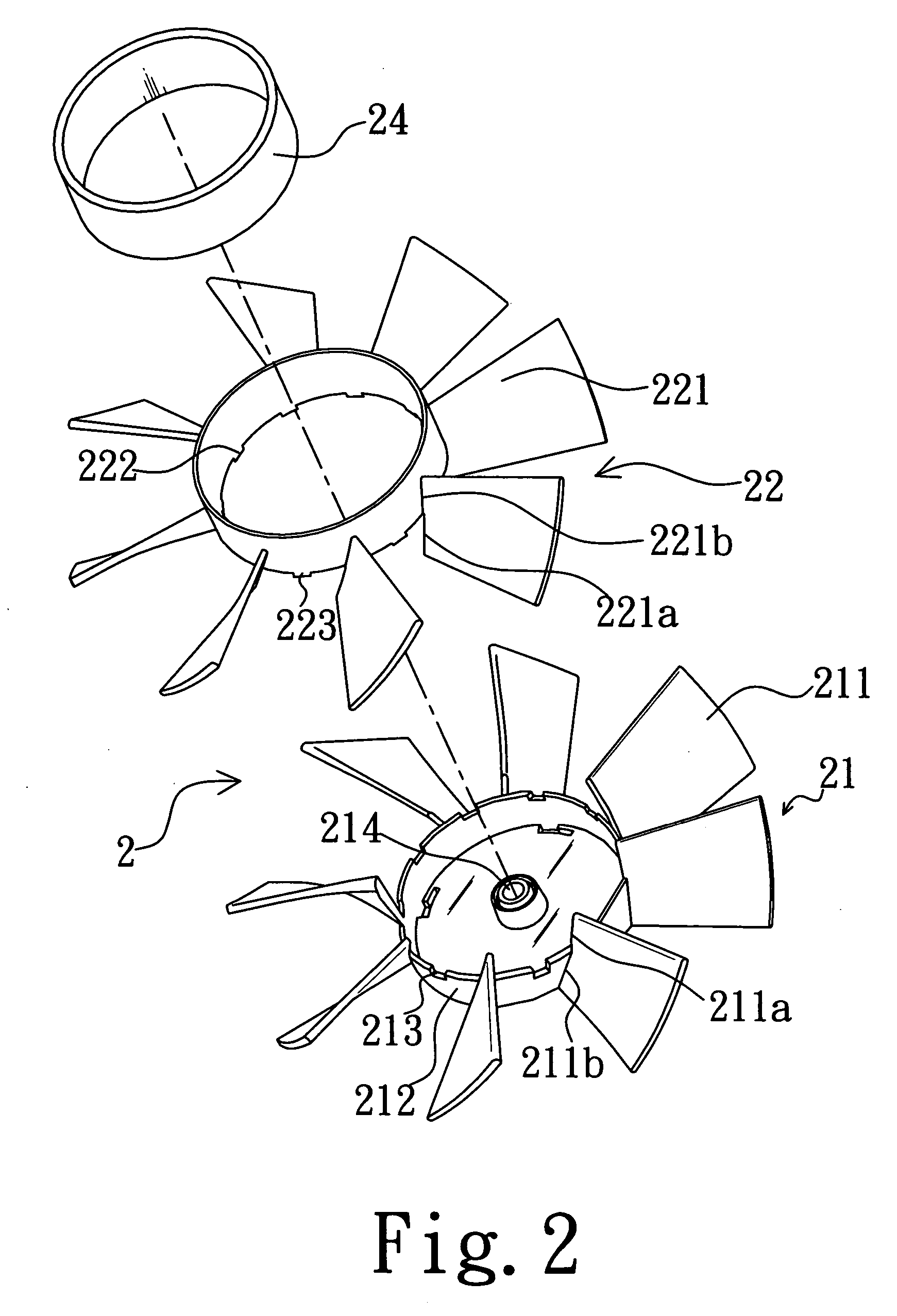
[0021]FIG. 2 is an explosive view showing a combination type fan leaves structure of a preferred embodiment according to the present invention, in which 2 is the entirety of the fan leaves structure.

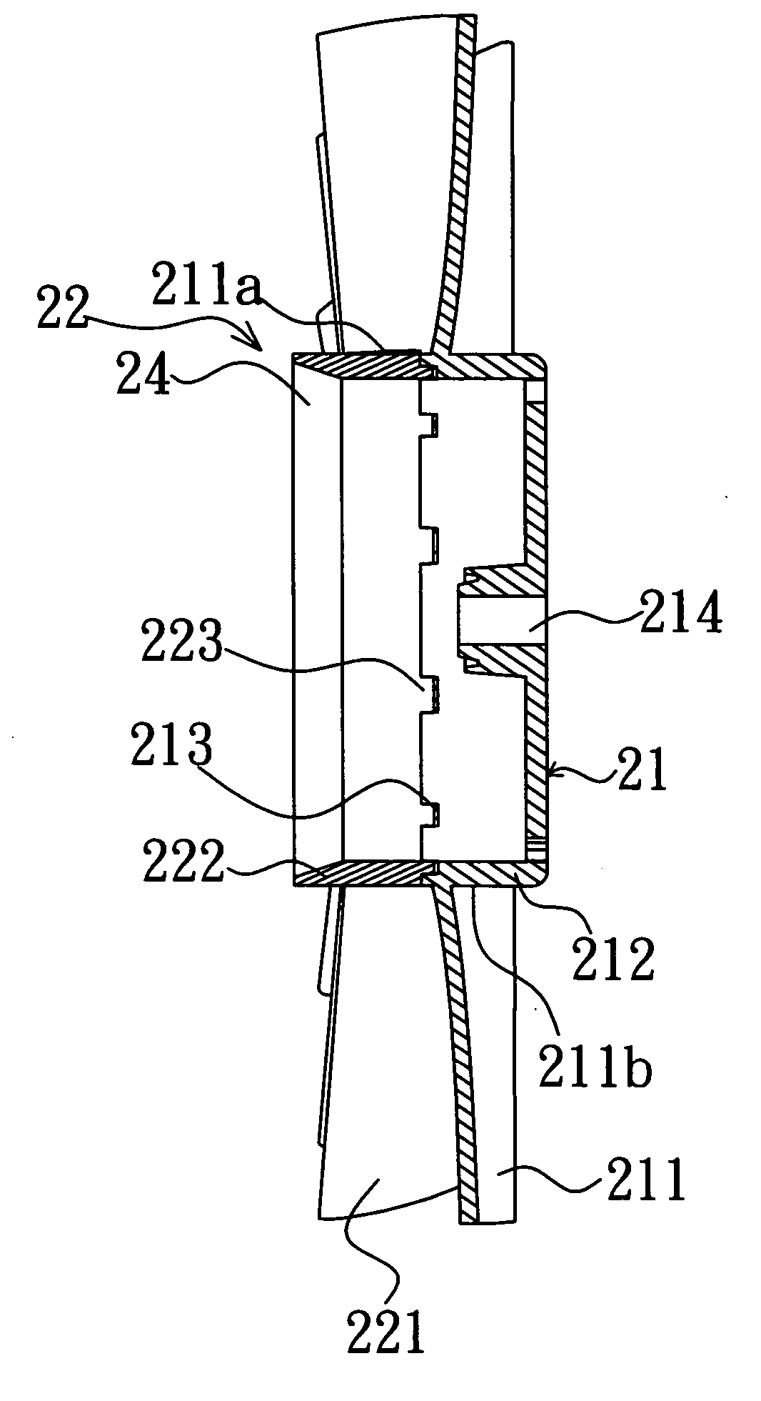
[0022] Please refer to FIGS. 2 and 3. The combination type fan leaves structure 2 comprises a upper fan leaves component 21, lower fan leaves component 22 and metal central supporting frame 24, in which the upper fan leaves component 21 further comprises a central cover 212 and fan leaves 211 connected on the central cover 212. One end 211b of each leaf 211 is connected to the cover 212 and another end of 211a is extended from the cover 212 and suspended in midair. A plurality of buckling units 213, which are used for buckling up with the lower fan leaves component 22, are disposed at the edge of the cover 212. Moreover, a fixing seat 214 installed at the center inside of the cover 212 is used for fixing a center shaft that is connected to a power supply (not shown in the figures) for d...


PUM


Abstract

A combination type fan leaves structure comprise a upper fan leaves component and lower leaves component; the leaves of the upper and lower leaves components are interlaced to combine into a high density leaves structure. Therefore, the mold release is easier so as to be contributive to the production of the fan leaves.

Description

BACKGROUND OF THE INVENTION [0001] 1. Field of the Invention [0002] The present invention relates to a combination type fan leaves structure, and more particularly to a fan leaves structure constituted by combining interlacing the leaves of the upper and lower leaves components to form a high density leaves structure. [0003] 2. Description of Related Art [0004] Accompanying the development of the computer technology, every kind of current electronic element has a great progress on work execution efficiency. But, that the temperature of the electronic element is too high owing to the increase of power consumption so that the electronic element is overheat, work abnormally or is even damaged. Consequently, a cooling fan has already become a necessary attachment for an electronic device. The air blowing magnitude of the cool fan influences a cooling efficiency directly and the larger the total area is, the more the air blowing magnitude of the cooling fan is. For increasing the total a...

Claims


Application Information

Patent Timeline
IPC IPC(8): F03D1/02
CPCF04D29/329
Inventor LAI, CHEN HUI
Owner POWER COOLER ENTERPRISE
Why Eureka
Try Eureka