Air jet type pipeline decontamination machine

a pipeline and jet-type technology, applied in sewer cleaning, sewer systems, construction, etc., can solve the problems of poor cleaning effect, low cleaning efficiency of traditional cleaning methods, and inability to effectively solve the sludge removal of pipelines, etc., and achieve the effect of large scraping force and more efficien

Inactive Publication Date: 2020-07-02
FANG DELAN
View PDF0 Cites 26 Cited by
  • Summary
  • Abstract
  • Description
  • Claims
  • Application Information

AI Technical Summary

Benefits of technology

[0004]The object of the present invention is to provide a jet propulsion pipeline decontamination machine, which can overcome the above-mentioned defects of the prior art, thereby improving the practicability of the equipment.
[0010]The beneficial effects of the present invention: The jet propelling pipeline decontamination machine provided by the present invention can realize the removal of sludge in the pipeline. The equipment uses the jet propelling equipment to drive the scraper to the depth of the pipeline and moves to the maximum limit. When the scraper is brought into contact with the pipe wall, and then the scraper is pulled out of the pipe by the wire drawing device, thereby scraping the sludge from the inner wall of the pipe, the device of the invention is thoroughly scraped, and the scraping force is large and more efficient.

Problems solved by technology

When the urban sewage pipeline is blocked, the traditional method of cleaning requires manual cleaning, which is not only very dangerous, but also has poor cleaning effect.
The traditional method of cleaning has low cleaning efficiency and cannot effectively solve the sludge removal of the pipeline.

Method used


Image

  • Air jet type pipeline decontamination machine
  • Air jet type pipeline decontamination machine
  • Air jet type pipeline decontamination machine

Examples


Embodiment Construction

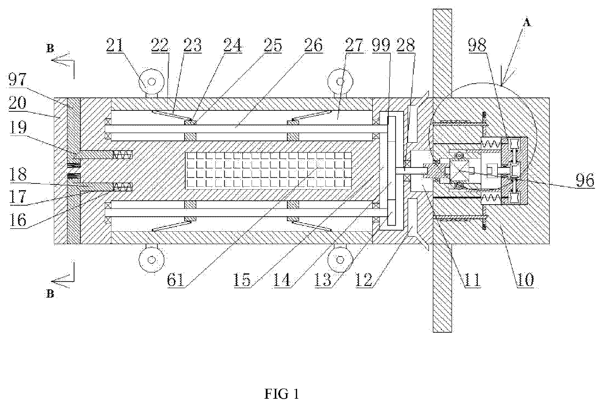
[0017]The present invention will be described in detail below with reference to FIGS. 1-4. For convenience of description, the orientation described below is defined as follows: the up-down, left-right, front-back direction described below is consistent with the up-down, left-right, front-back direction of the projection relationship of FIG. 1 itself.

[0018]A jet propulsion pipeline decontamination machine described in conjunction with FIGS. 1-4 includes a fuselage 10 and a fixing frame 20 provided on the left side of the fuselage 10. The center of the end wall of the fuselage 10 is symmetrically distributed. A gear lever 60 fixedly connected to the fuselage 10, four guide grooves 27 opening outward are symmetrically distributed in the center of the end wall of the fixing frame 20, and the left and right symmetrical grooves are slidably arranged in the guide groove 27. The moving block 24 is provided with a left and right threaded hole 25 with reverse threads passing through the left...


PUM


Abstract

The invention relates to the field of jet propulsion application, in particular to a jet propulsion pipeline decontamination machine, which includes a fuselage and a fixing frame provided on the left side of the fuselage. In the gear lever fixedly connected to the fuselage, four guide grooves opening outward are symmetrically distributed in the center of the end wall of the fixed frame, and left and right symmetrical moving blocks are slidably arranged in the guide groove. The moving block is provided with left and right threaded holes with reverse threads passing through the left and right, and the threaded holes are internally connected with threaded rods. The jet propelled pipeline decontamination machine provided by the present invention can realize the sludge in the pipeline. For cleaning, the equipment uses jet propelling equipment to drive the scraper to the depth of the pipeline. When it moves to the maximum limit, it drives the scraper to abut against the pipe wall, and then pulls the scraper to the outside of the pipe through the wire drawing device, thereby contaminating the inner wall of the pipe Mud scraping, the device of the invention is completely scraped, and the scraping force is large, which is more efficient.

Description

CROSS-REFERENCES TO RELATED APPLICATIONS[0001]The present application claims priority from Chinese application No. 201911121772X filed on Sep. 19, 2019 which is hereby incorporated by reference in its entirety.TECHNICAL FIELD[0002]The invention relates to the field of jet propulsion application, in particular to a jet propulsion pipeline decontamination machine.BACKGROUND OF THE INVENTION[0003]When the urban sewage pipeline is blocked, the traditional method of cleaning requires manual cleaning, which is not only very dangerous, but also has poor cleaning effect. The traditional method of cleaning has low cleaning efficiency and cannot effectively solve the sludge removal of the pipeline. Affecting the sewage discharge capacity of urban pipelines, it is necessary to set up a jet propulsion pipeline decontamination machine to improve the above problems.BRIEF SUMMARY OF THE INVENTION[0004]The object of the present invention is to provide a jet propulsion pipeline decontamination machi...

Claims


Application Information

Patent Timeline
Patent Type & Authority Applications(United States)
IPC IPC(8): E03F9/00B08B1/00B08B5/02B08B9/032B08B9/043
CPCB08B1/005B08B9/0436E03F9/002B08B5/02B08B9/0328B08B9/051
Inventor FANG, DELAN
Owner FANG DELAN
Why Eureka
Try Eureka