Optical system and imaging apparatus
a technology of optical system and imaging apparatus, applied in the field of optical system, can solve the problems of reducing the efficiency of substantial aperture, the space required for installing and mounting imaging apparatus, and the lens needs to have a wide angle, and achieve the effect of high magnification and high optical performan
- Summary
- Abstract
- Description
- Claims
- Application Information
AI Technical Summary
Benefits of technology
Problems solved by technology
Method used
Image

Examples
examples
[0095]Hereinbelow, the optical system according to the present invention and the imaging apparatus provided with the optical system will be described with reference to numerical value examples and the accompanying drawings.
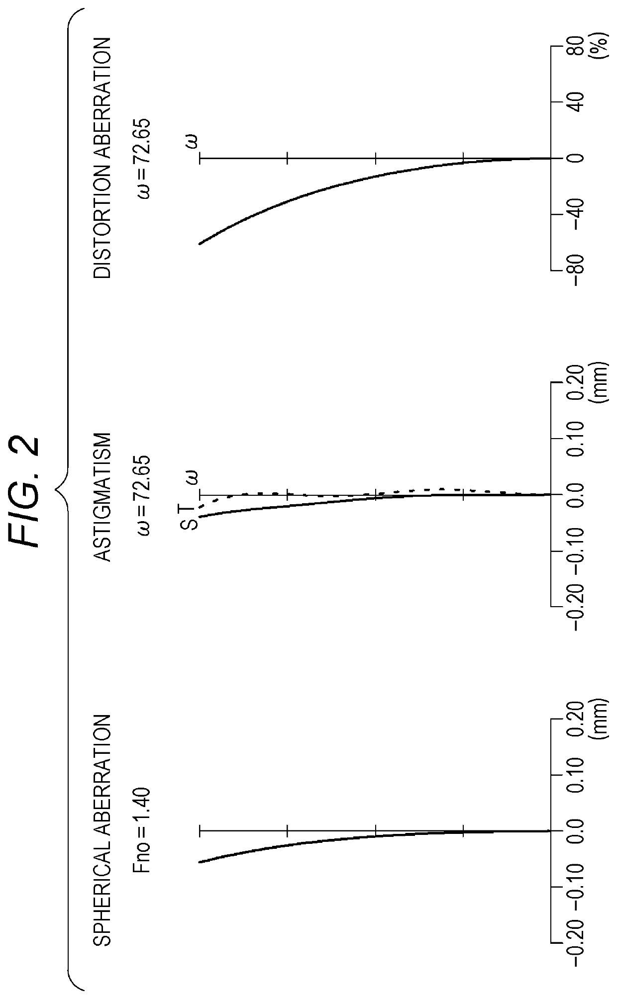
[0096]The numerical value examples to which specific numerical values of the optical system according to the present invention are applied will be described. In each table, f is the focal length of the total system, Fno is the F number, ω is the half angle of view, r is the radius of curvature, d is the lens thickness or lens interval, Nd is the refractive index at the d-line, νd is the Abbe number at the d-line, ASP affixed to the surface number indicates that the surface is an aspherical surface, and STOP indicates that an aperture stop is disposed. Further, each aspherical shape is represented by the following aspherical expression, where H is a height perpendicular to the optical axis, X(H) is a displaced amount in the optical axis direction at the height H wh...
first example
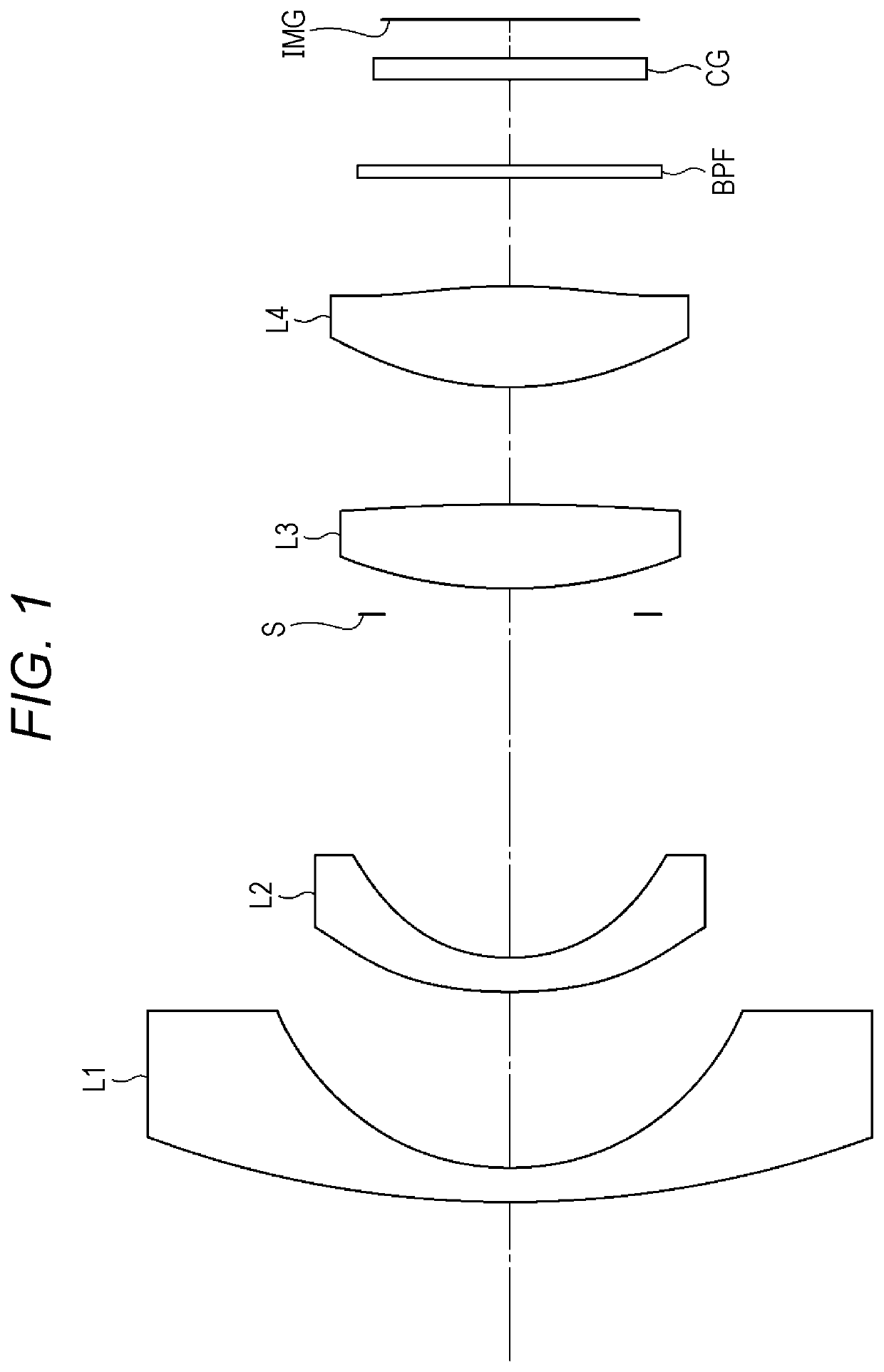
[0098]An optical system according to a first example includes a first lens L1 which has negative refractive power and has a meniscus shape convex to the object side, a second lens L2 which has negative refractive power, has meniscus shape convex to the object side, and has an aspherical shape on both faces thereof, a third lens L3 which has positive refractive power and has a biconvex shape, and a fourth lens L4 which has positive refractive power, has a biconvex shape, and has an aspherical shape on both faces thereof, the first lens L1, the second lens L2, the third lens L3, and the fourth lens L4 being disposed in this order from the object side. An aperture stop S is disposed between the second lens L2 and the third lens L3. A band-pass filter BPF is disposed between the fourth lens L4 and an imaging plane IMG. Further, the second lens L2 and the fourth lens L4 are resin lenses.
[0099]Although the band-pass filter BPF is disposed between the fourth lens L4 and the imaging plane I...
second example
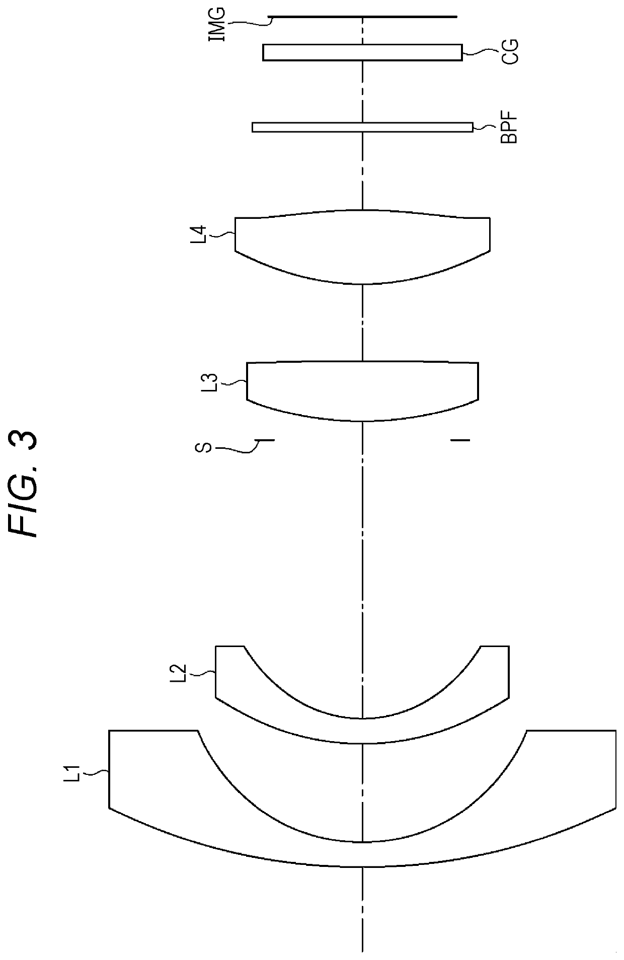
[0101]An optical system according to a second example includes a front lens group including a first lens L1 which has negative refractive power and has a meniscus shape convex to the object side and a second lens L2 which has negative refractive power, has a meniscus shape convex to the object side, and has an aspherical shape on both faces thereof, and a rear lens group including a third lens L3 which has positive refractive power and has a biconvex shape and a fourth lens L4 which has positive refractive power, has a biconvex shape, and has an aspherical shape on both faces thereof, the first lens L1, the second lens L2, the third lens L3, and the fourth lens L4 being disposed in this order from the object side. An aperture stop S is disposed between the second lens L2 and the third lens L3. A band-pass filter BPF is disposed between the fourth lens L4 and an imaging plane IMG. Further, the second lens L2 and the fourth lens L4 are resin lenses.
[0102]Although the band-pass filter ...
PUM
 Abstract
Description
Claims
Application Information
 - R&D
- Intellectual Property
- Life Sciences
- Materials
- Tech Scout
- Unparalleled Data Quality
- Higher Quality Content
- 60% Fewer Hallucinations
Browse by: Latest US Patents, China's latest patents, Technical Efficacy Thesaurus, Application Domain, Technology Topic, Popular Technical Reports.
© 2025 PatSnap. All rights reserved.Legal|Privacy policy|Modern Slavery Act Transparency Statement|Sitemap|About US| Contact US: help@patsnap.com