
Dynamic bus routing

a technology of dynamic bus routing and transportation, applied in traffic control systems, navigation instruments, instruments, etc., can solve the problems of increased road congestion, increased resource consumption, wear on transportation infrastructure, and loss of productivity of commuters on long trips between home and work, so as to improve commuting solutions

Inactive Publication Date: 2020-07-02
PROTERRA OPERATING CO INC
View PDF0 Cites 5 Cited by
  • Summary
  • Abstract
  • Description
  • Claims
  • Application Information

AI Technical Summary

Benefits of technology

The patent describes a system and method that can coordinate TNC services and commuter bus schedules with dynamic route and schedule adjustments. This can improve commuting solutions and make it easier for people to get to their destinations on time.

Problems solved by technology

This reliance on personal automobiles—often with a single occupant—may result in increased road congestion, air pollution, resource consumption, and wear on transportation infrastructure.
In addition, commuters on long trips between home and work suffer from lost productivity while commuting.
Public transit is cost-effective, but inconvenient, while TNCs may be convenient but not cost-effective.
At the same time, TNC operators seeking to expand their service offerings may provide a shared commute service, but the high cost of a human driver makes the service too expensive for all but the shortest commutes, even for rides shared by multiple commuters.
Public transit, such as by commuter bus, provides a low cost per passenger mile, but rigid schedules and a limited number of access points makes such a service inconvenient for a majority of commuters.
For this reason, most commuters do not consider public transit as a viable solution to their commutes.
Furthermore, an individual commuter lacks the ability to coordinate TNC services and commuter bus schedules to achieve a seamless and convenient combined commuting solution.

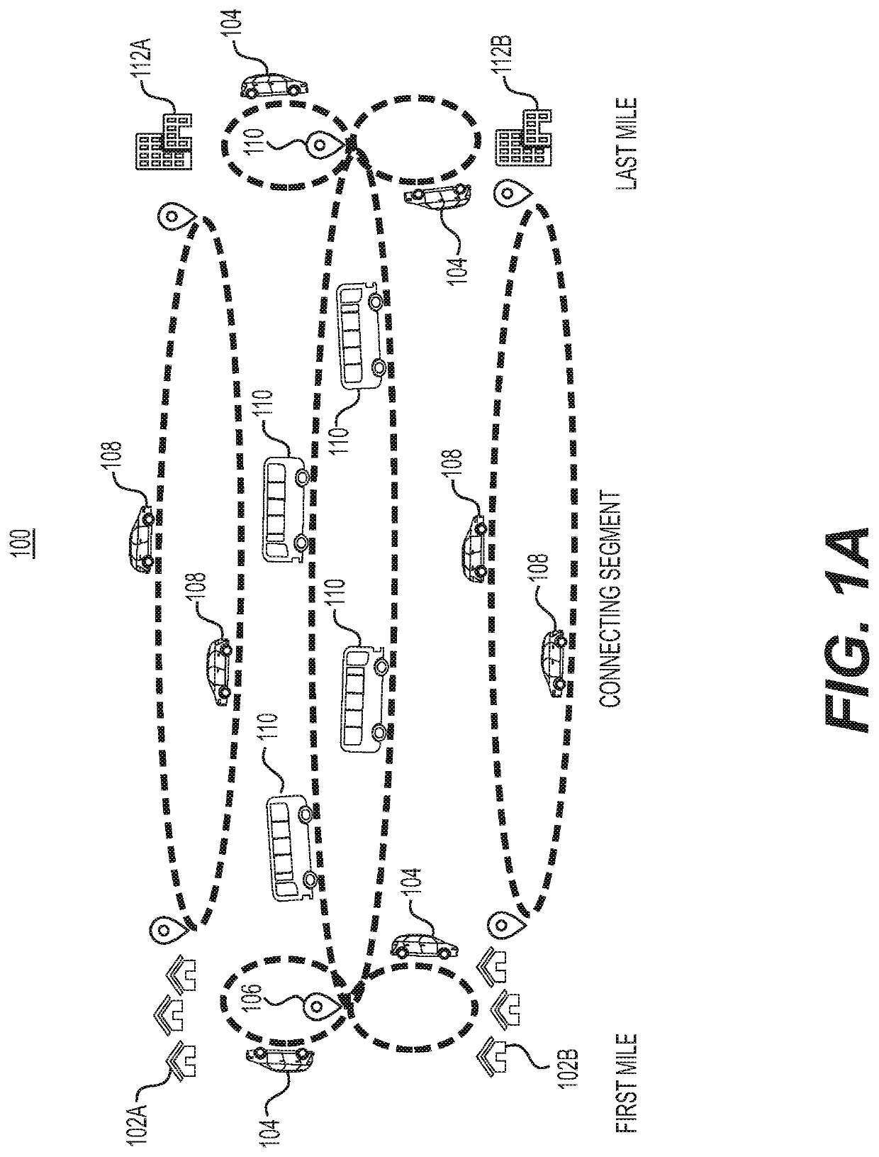
Method used


Image

  • Dynamic bus  routing
  • Dynamic bus  routing
  • Dynamic bus  routing

Examples


Embodiment Construction

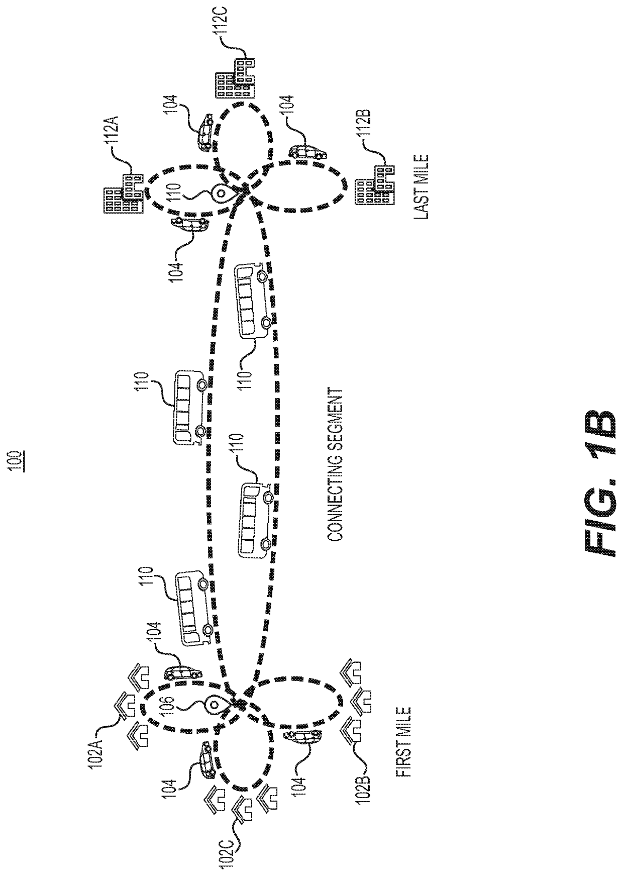
[0020]Various embodiments of the present disclosure relate generally to providing dynamic routing of commuter buses and other means of transportation.

[0021]The terminology used below may be interpreted in its broadest reasonable manner, even though it is being used in conjunction with a detailed description of certain specific examples of the present disclosure. Indeed, certain terms may even be emphasized below; however, any terminology intended to be interpreted in any restricted manner will be overtly and specifically defined as such in this Detailed Description section.

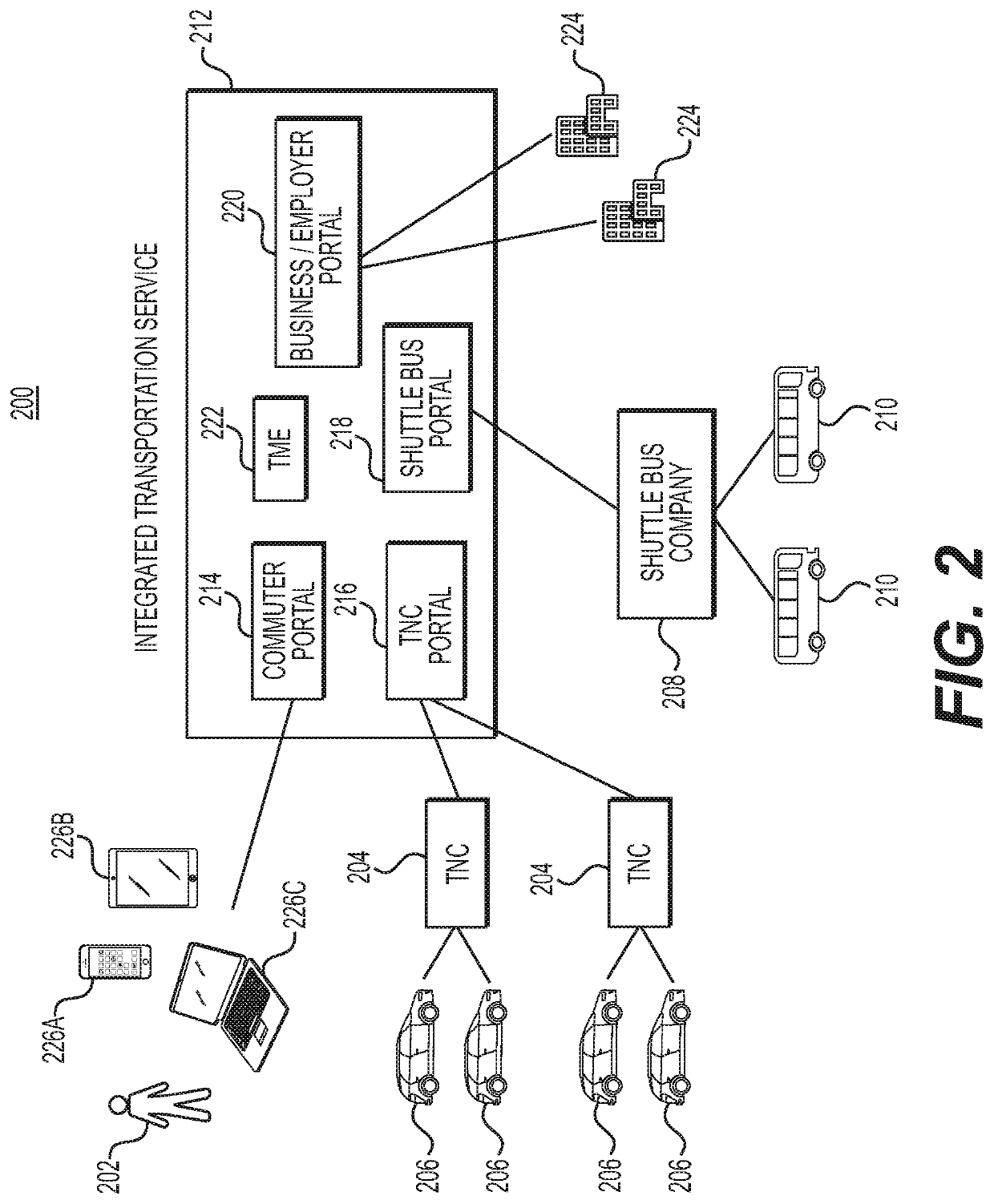
[0022]Any suitable system infrastructure may be put into place to allow dynamic bus routing. FIGS. 1-3 and 6 and the following discussion provide a brief, general description of a suitable environment in which the present disclosure may be implemented. In one embodiment, any of the disclosed systems, methods, and / or graphical user interfaces may be executed by or implemented by a computing system consistent with o...


PUM


Abstract

A computer-implemented method for dynamic bus routing includes receiving a request from a commuter for transportation from an origin to a destination, determining a commuter bus route to service the commuter request, determining a transportation network company (TNC) schedule from the origin to a commuter bus pick-up point for the commuter, scheduling a commuter bus trip from the commuter bus pick-up point to a commuter bus drop-off point for the commuter, determining a TNC schedule from the commuter bus drop-off point to the destination for the commuter, dispatching a first TNC driver to the origin for the commuter and scheduling a dispatch of a second TNC driver to the commuter bus drop-off point for the commuter.

Description

CROSS-REFERENCE TO RELATED APPLICATIONS[0001]This application claims the benefit of U.S. Provisional Application No. 62 / 786,072, filed Dec. 28, 2018, the disclosure of which is incorporated herein by reference in its entirety.TECHNICAL FIELD[0002]Various embodiments of the present disclosure relate generally to routing and scheduling for public transportation systems and, more particularly, to dynamic routing and coordination of transportation provided by transportation network companies (TNCs) and commuter buses.BACKGROUND[0003]In many urban and suburban commuting environments, commuters may travel from a dense residential neighborhood to a distant dense business district. For reasons of convenience, commuters commonly rely on personal automobiles for such a commute even though alternatives, such as transportation network companies (TNCs) and commuter buses are available. This reliance on personal automobiles—often with a single occupant—may result in increased road congestion, air...

Claims


Application Information

Patent Timeline
Patent Type & Authority Applications(United States)
IPC IPC(8): G06Q50/26G06Q10/06G01C21/34G06Q10/04
CPCG06Q10/047G01C21/3415G06Q10/06311G06Q10/06312G08G1/123G06Q50/26G01C21/3423G01C21/3438G08G1/127G08G1/005G08G1/202G06Q10/06315G06Q50/40
Inventor HORTON, MATTHEW
Owner PROTERRA OPERATING CO INC
Learn More