Engine system

Inactive Publication Date: 2020-07-09
AISAN IND CO LTD
View PDF0 Cites 2 Cited by
  • Summary
  • Abstract
  • Description
  • Claims
  • Application Information

AI Technical Summary

Benefits of technology

The configurations described in this patent prevent the inflow of evaporated fuel from the engine to the cat during a fuel cut. This helps to prevent the temperature of the cat from rising too much and causing damage. Additionally, the configuration can improve the timing for performing a purge cut to avoid overheating the cat and to maintain a proper air-fuel ratio. Overall, these configurations help to protect the engine from malfunctions and ensure optimal performance.

Problems solved by technology

Therefore, even if purge cut is performed at the same time as fuel cut during deceleration, residual intake air containing vapor continues to flow into the catalyst, thereby causing an excessive rise of the temperature of the catalyst, resulting in such an overheat that the catalyst is deteriorated or eroded.

Method used


Image

  • Engine system
  • Engine system
  • Engine system

Examples


first embodiment

[0057]A detailed description of a first embodiment of an engine system embodying the present disclosure will now be given referring to the accompanying drawings.

[0058](Overview of Engine System)

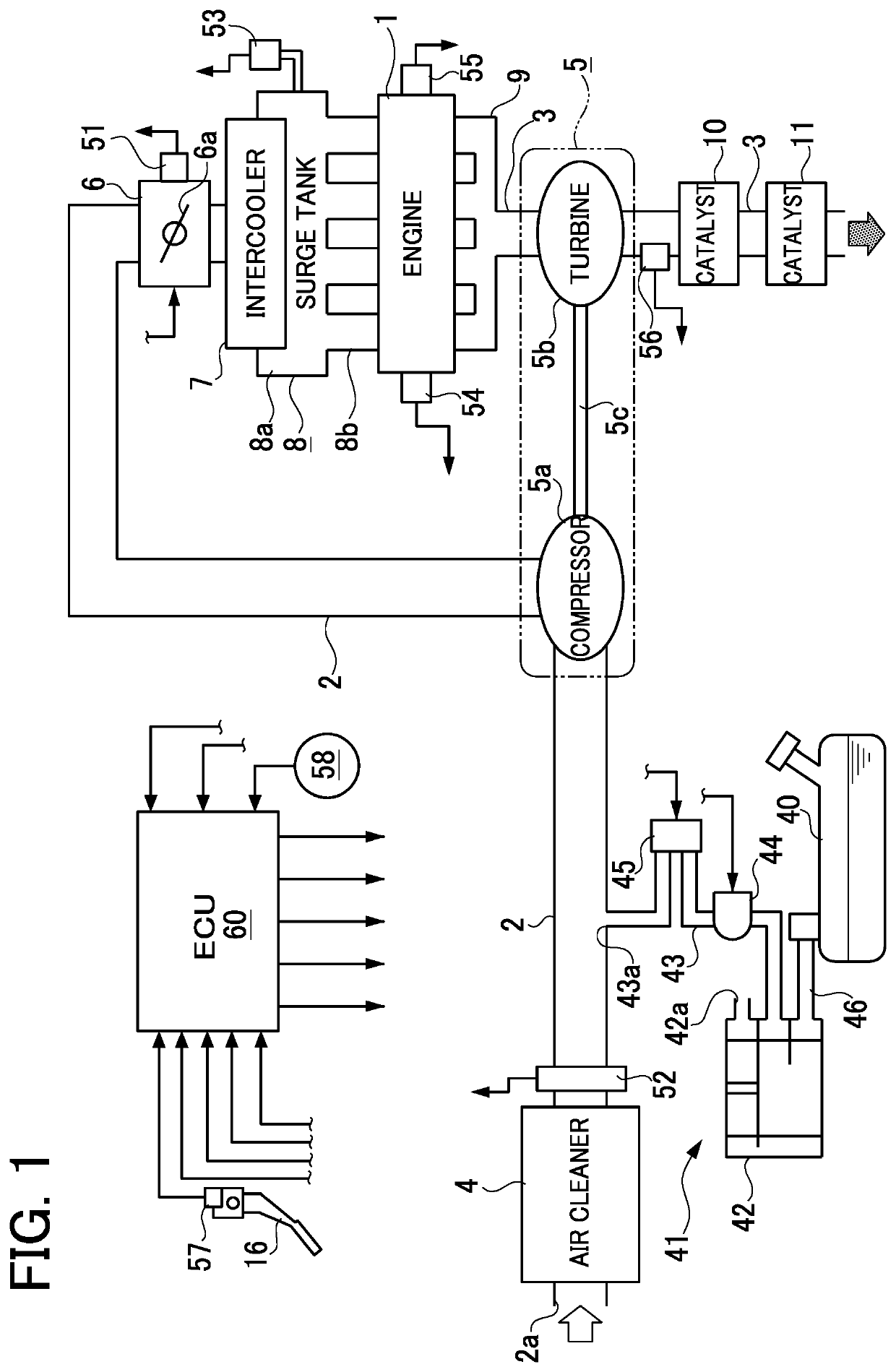
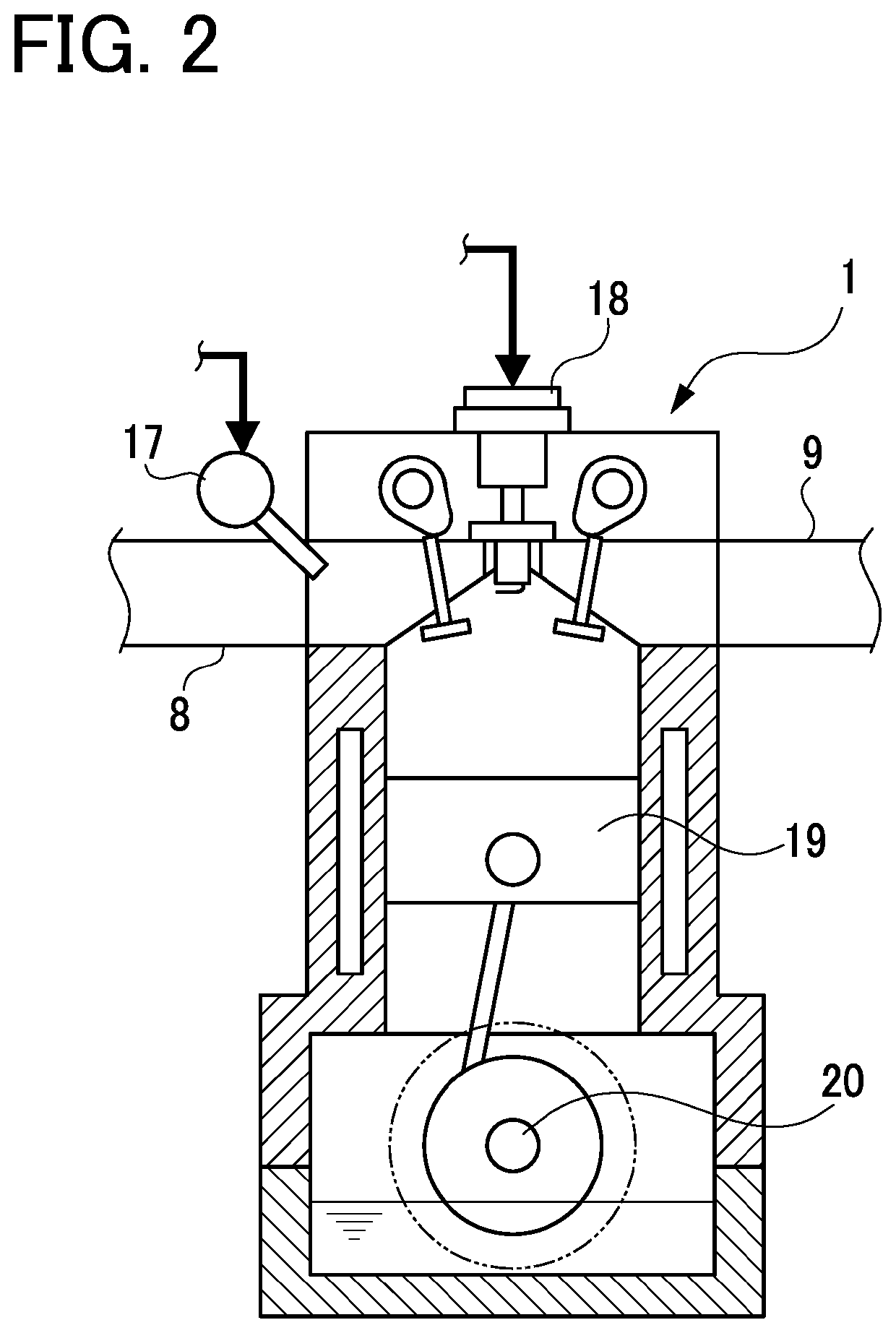
[0059]FIG. 1 is a schematic configuration view showing the engine system in the present embodiment. A gasoline engine system installed in an automobile (hereinafter, simply referred to as an “engine system”) includes an engine 1 having a plurality of cylinders. This engine 1 is a four-cylinder, four-cycle reciprocating engine, and includes well-known components, such as a piston 19 and a crankshaft 20 (see FIG. 2) which will be described later. The engine 1 is provided with an intake passage 2 configured to introduce intake air into each of the cylinders, and an exhaust passage 3 configured to discharge exhaust gas from each cylinder. A supercharger 5 is provided in the intake passage 2 and the exhaust passage 3. In the intake passage 2, an intake inlet 2a, an air cleaner 4, a compressor 5a o...

second embodiment

[0106]A detailed description of a second embodiment of an engine system embodying the present disclosure will now be given referring to the accompanying drawings.

[0107]In the following description, components similar or identical to those in the first embodiment will be assigned the same reference signs as in the first embodiment and their details are omitted. Differences from the first embodiment will be mainly described below.

[0108](Purge Control During Deceleration)

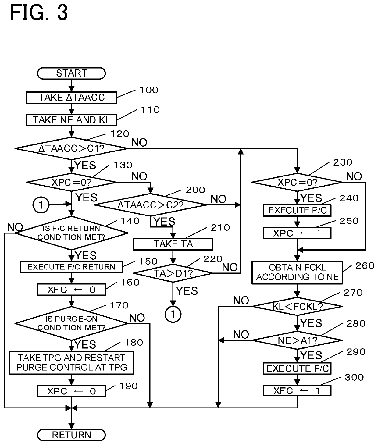
[0109]The present embodiment differs in contents of the purge control from the first embodiment. FIG. 6 is a flowchart showing the contents of the purge control.

[0110]In the second embodiment, a flowchart in FIG. 6 additionally includes the processes in step 400 and step 410 prior to the process in step 230, differently in configuration from the flowchart in FIG. 3.

[0111]Specifically, in this routine, in step 400 following step 120, step 200, or step 220, the ECU 60 takes the throttle opening degree TA based on a detec...

third embodiment

[0116]A detailed description of a third embodiment of an engine system embodying the present disclosure will now be given referring to the accompanying drawings.

[0117](Purge Control During Deceleration)

[0118]The present embodiment differs in some contents of the purge control from the second embodiment. FIG. 8 is a flowchart showing the contents of the purge control.

[0119]In the present embodiment, the flowchart in FIG. 8 differs from the flowcharts in FIGS. 3 and 6 in the processes in step 420 to step 440, which are added prior to the process in step 230.

[0120]Specifically, in this routine, in step 420 following step 120, step 200, or step 220, the ECU 60 obtains a small opening degree D2NE corresponding to the engine rotation speed NE. The ECU 60 can obtain this small opening degree D2NE corresponding to the engine rotation speed NE by referring to for example a small opening degree map as shown in FIG. 9. In this map, the small opening degree D2NE is set to be higher in a curve a...


PUM


Abstract

This engine system is provided with: an engine; an injector; a super charger (including a compressor); an electronic throttle device provided in an air intake passage, the compressor being provided in the air intake passage upstream of the electronic throttle device; an evaporated fuel treatment apparatus (including a canister, a purge passage, and a purge valve), an outlet of the purge passage being connected to the air intake passage upstream of the compressor; and an electronic control unit (ECU). The ECU controls the purge valve in order to perform a purge cut of the vapor from the purge passage toward the air intake passage when determining that the engine has started to decelerate, and thereafter controls the injector in order to perform fuel cut to the engine.

Description

TECHNICAL FIELD[0001]The technique disclosed in this specification relates to an engine system including an engine equipped with a supercharger, an intake air amount regulating valve for regulating an intake air amount of the engine, and an evaporated fuel treatment apparatus for treating evaporated fuel generated in a fuel tank, the engine system being configured to control the intake air amount regulating valve and the evaporated fuel treatment apparatus during deceleration of the engine.BACKGROUND ART[0002]Conventionally, as a technique of the above type, for example, there has been known an “internal combustion engine equipped with a supercharger” described in Patent Document 1 described below. This technique includes an engine equipped with a supercharger, an electronic throttle device for adjusting an intake air amount of the engine, a fresh air introduction device for introducing fresh air downstream of the electronic throttle device (including a fresh air introduction passag...

Claims


Application Information

Patent Timeline
IPC IPC(8): F02D41/12F02D43/00F02B37/00F02M25/08
CPCF02D41/12F02M25/08F02D43/00F02B37/00F02D23/02F02D41/0007F02D41/0032F02D41/123F02D41/126Y02T10/12
Inventor YOSHIOKA, MAMORU
Owner AISAN IND CO LTD
Why Eureka
Try Eureka