Methods and devices for a building monitoring system

a technology for monitoring systems and buildings, applied in testing/monitoring control systems, heating types, instruments, etc., can solve problems such as wasting valuable time, adding an extra expense for an unnecessary visit, and only appearing problems

Active Publication Date: 2020-07-16
PRICEMY DEVELOPER LLC
View PDF2 Cites 10 Cited by
  • Summary
  • Abstract
  • Description
  • Claims
  • Application Information

AI Technical Summary

Benefits of technology

[0016]The wetness shutoff valve can be removably, attached to the building's main water supply. The wetness shutoff valve can replace or be placed inline next to the building's water main shutoff valve. The wetness shutoff valve can be electronic wherein an electric motor can turn the valve to the on and off positions, and the wetness shutoff valve can be connected to a wireless communication system wherein the user can have access the wetness shutoff valve remotely. A method of monitoring a location for wetness comprising detecting wetness through at least one wetness detector, monitoring the state of a shutoff valve to determine if the shutoff valve is in an open or a closed state, notifying a user of a change the at least one wetness detector or state of the shutoff valve, and allowing a steward to remotely close and / or open the shutoff valve. The user can determine the location of the wetness detector within a building through a computing device.

Problems solved by technology

There are several problems with regularly schedule maintenance that can cause both residential and business owners problems without knowing the root cause of the problem, a technician can sometimes spend hours if not days' troubleshooting the customer's HVAC system.
For example, a problem may only appear when the refrigerant flows thru the condenser and triggers the float valve.
If this occurs the technician is wasting valuable time driving to the residence, or commercial building to troubleshoot and repair the system.
In addition, a maintenance call may not be necessary if the coolant levels are correct, air filters are clean, and the HVAC system is running within its standard ranges adding an extra expense for an unnecessary visit.
Furthermore, a technician may miss a faulty part, or a part that is about ready to fail during the routine maintenance inspection which may end up costing the owner more in repeat visits.
These types of systems can only run diagnostics, give a user a limited amount information when a fault is detected, and usually are integrated within, or interfere with the system and cannot be bypassed.
Furthermore, current HVAC monitoring systems can be controlled remotely through a user's computing device, but these type of systems are limited to controlling the temperature or air flow remotely, or the HVAC system comes with a monitoring system already incorporated into the condenser unit and air handler unit, which limits the user to very specific components being monitored within the system.
In addition, there is currently not a system that incorporates a HVAC monitoring system with an on-demand service for requesting a technician service if the HVAC monitoring systems gives an error.
Water leaks are common problems around air conditioners, hot water heaters, washing machines, toilets, and various other water-dependent appliances used in residential and commercial buildings.
While HVAC systems may not consist of water, it does however use refrigerant cooling, which still threatens homes and / or businesses if not properly drained.
Water leaks are unpredictable and can happen at any time of the day and are detected only when a substantial amount of water has accumulated.
This problem further is exacerbated by aging appliances and plumbing and deteriorating joints.
Unpredictable and untimely water leaks are always inconvenient and can cause incidental damage to furniture, electrical equipment, flooring, and other property.
However, developments in the art only address monitoring and detecting leaks throughout a residence and business in usually one area with audible alarms.

Method used


Image

  • Methods and devices for a building monitoring system
  • Methods and devices for a building monitoring system
  • Methods and devices for a building monitoring system

Examples


Embodiment Construction

[0041]The embodiments of the invention described herein are not intended to be exhaustive or to limit the invention to precise forms disclosed. Rather, the embodiments selected for description have been chosen to enable one skilled in the art to practice the invention.

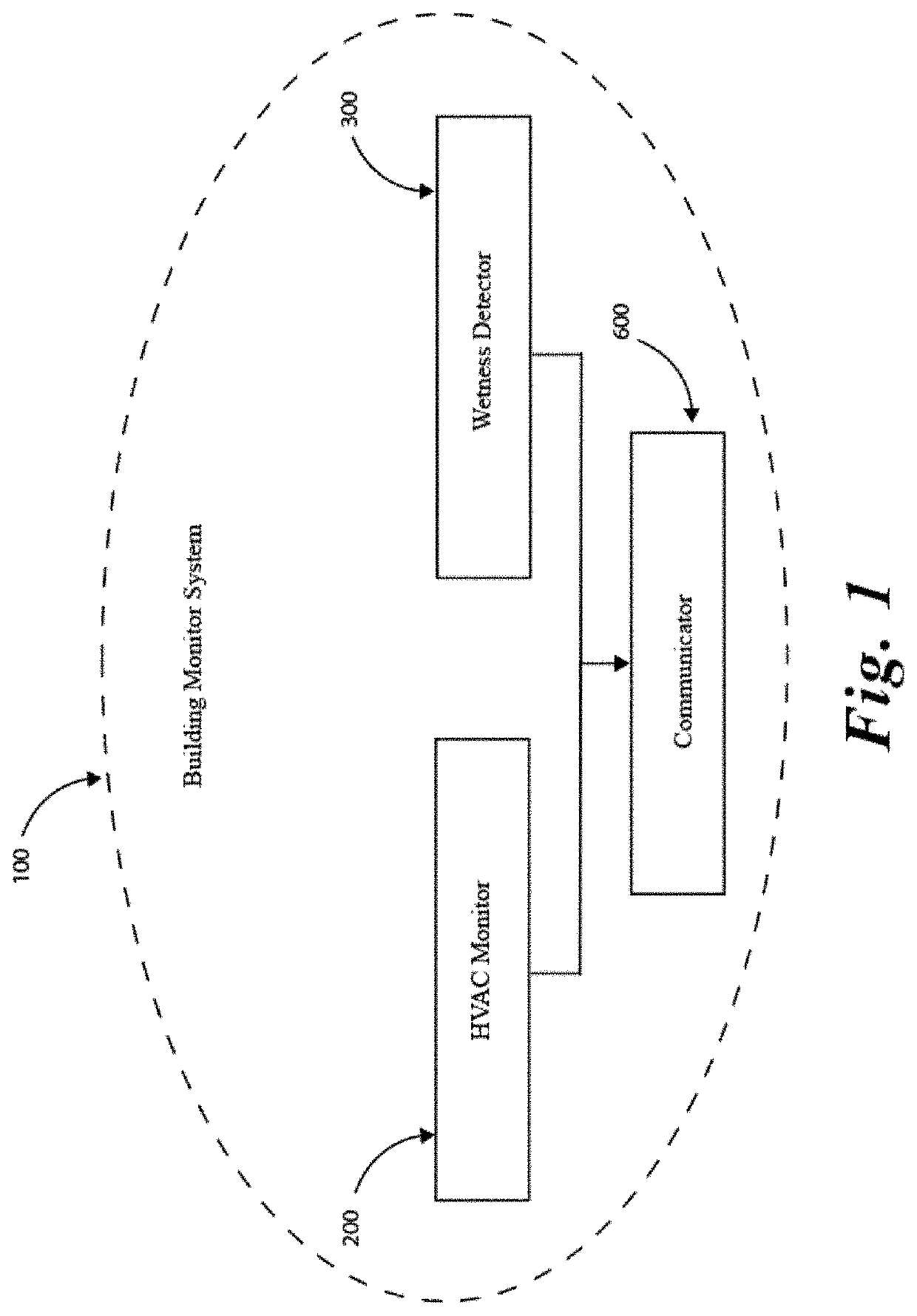
[0042]FIG. 1 illustrates a general overview of a building monitoring system 100. In embodiments, a building monitoring system 100 can comprise a HVAC monitor 200 comprising a condensing unit connector, a wetness monitor system 300, and a communicator 900 wherein a communicator accesses a location of the building monitoring system and selectively communicates with a technician or a user based at least in part on the location.

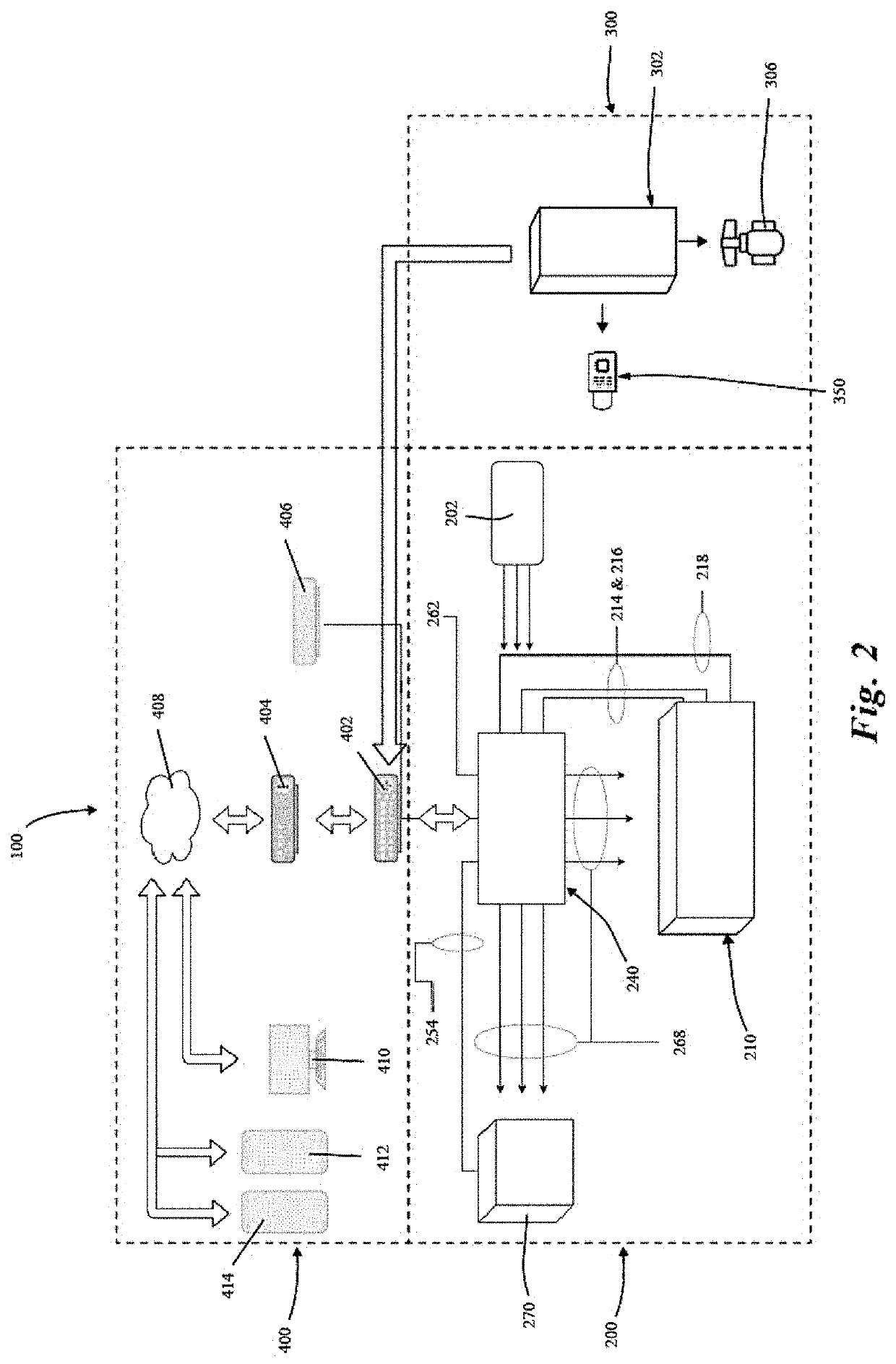
[0043]Referring to FIG. 2, illustrates a high-level functional block diagram of a building monitoring system shown generally at 100. The control module or HVAC monitor 200 can comprise a monitoring center module 240, a condenser module 270 attached to a condenser unit 272 (often, outdoors), and an a...


PUM

PropertyMeasurementUnit
temperatureaaaaaaaaaa
humidityaaaaaaaaaa
pressureaaaaaaaaaa

Abstract

A building monitoring system, wherein the system comprises an HVAC monitor, which comprised a condensing unit connector, an air handler connector, a thermostat connector and a control module, a wetness detector; and a communicator. The communicator accesses a location of the building monitoring system and selectively communicates with a technician based at least in part on the location. A monitor system for use with an existing HVAC unit, wherein the HVAC unit has a condenser or furnace, an air handler, and a thermostat, the HVAC monitor system comprising at least one condenser or furnace sensor, at least one air handler sensor and at least one control module. A wetness monitor system, comprising at least one wetness detector connected to a control, wherein the control is also connected to a network and the network is connected to a flow shutoff valve. A method of monitoring a location for wetness comprising detecting wetness through at least one wetness detector, monitoring the state of a shutoff valve.

Description

CROSS-REFERENCE TO RELATED APPLICATIONS[0001]This application claims benefit from currently pending U.S. Provisional Application No. 62 / 792,713 titled “Methods and Devices for a Building Monitoring System” and having a filing date of Jan. 15, 2019, all of which is incorporated by reference herein.BACKGROUND OF THE INVENTIONField of the Invention[0002]The present invention relates to heating, ventilation, and air condition system (“HVAC”) system, an active leak detection system and an active alert and monitoring system, and more particular an intelligent residence, or building that remotely monitors, provides diagnostics, and alerts a user or gives a technician real-time updates on the system allowing for an on-demand technician service model.Description of Related Art[0003]Various types of devices for creating an intelligent residence or building exist in the art, more particular for monitoring and controlling residential or commercial HVAC systems and plumbing systems, and then ale...

Claims


Application Information

Patent Timeline
Patent Type & Authority Applications(United States)
IPC IPC(8): G05B23/02G05D7/06G01N27/02F24F11/36F24F11/58F24F11/52
CPCG05D7/0635F24F11/58G01N27/02G05B23/0272F24F11/36F24F11/52G05B23/0267F24F2140/00
Inventor LAMONT, JOHNNIELSON, LESLIEPESCATORE, ROBERT
Owner PRICEMY DEVELOPER LLC
Why Eureka
Try Eureka