Implantable Sensor and Method for Such Sensor

a bioimpedance and implantable technology, applied in the field of implantable medical devices and implantable sensors for measuring bioimpedance, can solve the problems of inconvenience of repeated blood sample drawing, margin of error, and inconvenient use of implantable pacemakers and implantable cardioverters-defibrillators, and achieves convenient and fast production, small size, and long service life.

Inactive Publication Date: 2019-08-22
D T R DERMAL THERAPY RES
View PDF0 Cites 1 Cited by
  • Summary
  • Abstract
  • Description
  • Claims
  • Application Information

AI Technical Summary

Benefits of technology

[0015]In accordance with broad aspects of the present invention, there is provided an implantable sensor for measuring or detecting one or more user related parameters, for example, physiologic parameters. The measured parameter can be remotely accessed by, for example, a hand held reader to obtain sensed parameters values in a non-invasive manner. The sensor does not use any on-board power sources and thus the sensor will never need to be removed from an implantation site in order to replace an electrical power source, and can therefore remain implanted for an indefinite period of time. Accordingly, the present invention provides for an effective monitoring and follow-up of user related conditions or parameters such as different physiological parameters including hydration, glucose levels etc., health status, drug compliance, in connection with organ transplantations to monitor the vitality of an organ during transportation from donor to recipient, and to monitor signs of rejection, infections or ischemia, monitor the ovarian cycle using e.g. temperature, and monitoring glucose and hydration to identify alertness of aviators, truck drivers etc. The present invention provides further an improved implantable sensor that is small, reliable, easy and cheap to produce and that can be carried over extended periods of time without need for re-charge or change of battery.
[0017]A remote reader module can be used to energize the device, such as with electromagnetic energy, to thereby cause the device to sense the physiologic parameter values and to transmit the data representative thereof to the remote reader.
[0018]Due to its small size and the absence of a need of an on-board electrical power source, the sensor according to the present invention is particularly suitable for human implantation and can remain implanted for an indefinite period of time.
[0019]The detector in the implantable sensor uses one path to extract the I and Q components of the signal. The result of the I / Q demodulation is a DC signal, which entails that the extraction of the I and Q components can be performed when required or desired. This is in contrast to prior art I / Q demodulation in communication systems, where phase and amplitude change over time and the processing therefore has to be performed in parallel. The solution according to the present invention leads to significant reduction in power consumption since only one path needs to be active. This is of importance in the present invention since limited power can be extracted from the inductive coupling. This also entails that sensor itself can be made smaller.

Problems solved by technology

Obviously, implantable pacemakers and implantable cardioverters-defibrillators (ICDs) are not suitable for such a system.
There are numerous drawbacks to this method, for example, the patient have to draw samples of blood every day, several times a day at regular intervals, and there is some discomfort associated with drawing blood samples repeatedly.
In addition, there is a margin of error, for example, the patient may forget to take a blood sample.
Such glucose sensors must perform properly; otherwise, false data may be provided.
Such false data (if acted upon) could result in the administration of an inappropriate amount of insulin, leading to death or serious injury.
The sensor described in this article has however only a limited working life since it consumes itself during use.

Method used


Image

  • Implantable Sensor and Method for Such Sensor
  • Implantable Sensor and Method for Such Sensor
  • Implantable Sensor and Method for Such Sensor

Examples


Embodiment Construction

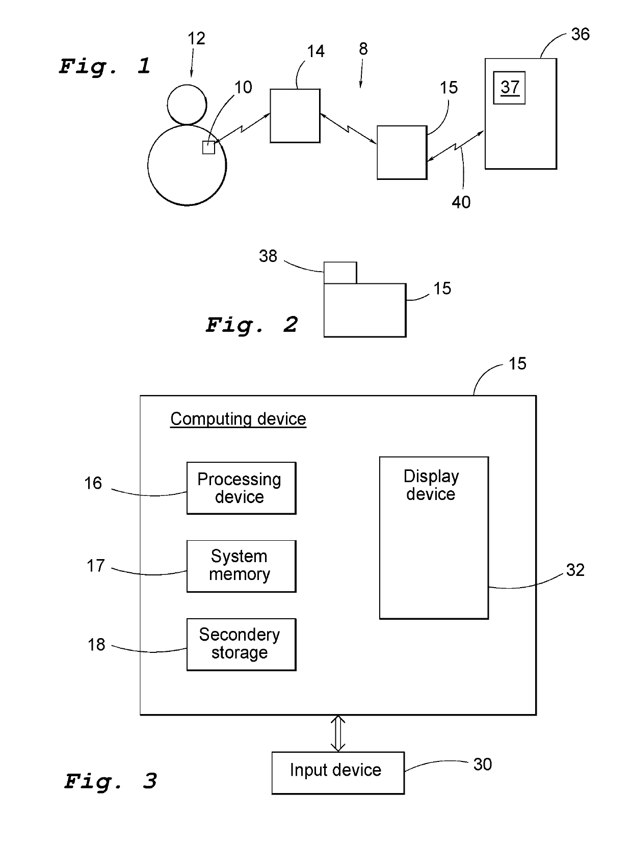
[0067]With reference first to FIG. 1, an embodiment of a system for measuring or monitoring user related conditions or parameters such as different physiological parameters including hydration, glucose levels etc., health status, drug compliance, in connection with organ transplantations to monitor the vitality of an organ during transportation from donor to recipient, and to monitor signs or rejection, infections or ischemia, monitor the ovarian cycle using e.g. temperature, and monitoring glucose and hydration to identify alertness of aviators, truck drivers etc. There is clearly a need of such a system that can be used with small, reliable, easy and cheap to produce and that can be carried over extended periods of time will be described. In preferred embodiments of the invention, the system uses a sensor that measures the impedance of body tissue and the impedance measurements are used to detect or monitor glucose levels.

[0068]A sensor 10 for measuring electrical bio-impedance of...


PUM


Abstract

The present invention relates to an implantable sensor configured to be implanted within the body of the subject and being configured to measure impedance within a body tissue of the subject resulting from an electrical current flowing through the body tissue, wherein the body tissue is sub-dermal or subcutaneous tissue of the subject. One pair of injection electrodes is configured for injection of electrical current into the body tissue and one pair of sensing electrodes is configured to detect the resulting voltage. A detector is operatively connected to the sensing electrodes and is configured to receive the voltage detected by the sensing electrodes, wherein the detector is configured to measure the impedance of the body tissue based on the voltage detected by the pair of sensing electrodes. A microcontroller is operatively connected to the detector and is configured to receive impedance signals from the detector and to provide control signals to the current signal output circuit and a powering and communication circuit including a coil configured to be powered by an electromagnetic field produced by an external coil.

Description

FIELD OF THE INVENTION[0001]The present invention relates to the field of implantable medical devices and implantable sensor for measuring bio-impedance. In particular embodiments of the present invention, it relates to sensors that can be implanted into a body to detect or measure at least one physiological parameter of the body such a blood glucose levels.BACKGROUND OF THE INVENTION[0002]Up to the present time, effective monitoring and follow-up of user related conditions or parameters such as different physiological parameters, health status, drug compliance has been limited to user's wearing implantable pacemakers and implantable cardioverters-defibrillators (ICDs). Current devices allow access to multiple critical data points reflecting device functionality and overall clinical condition of the user. The most recent advancements in device follow-up has provided for easier access to device stored data by utilizing wireless connectivity and internet based access to data as comple...

Claims


Application Information

Patent Timeline
Patent Type & Authority Applications(United States)
IPC IPC(8): A61B5/053A61B10/00A61B5/00A61B5/07A61B5/145
CPCA61B5/0538A61B10/0012A61B5/0031A61B5/053A61B5/076A61B5/6867A61B5/7225A61B5/7228A61B5/14532A61B5/4878A61B5/4318A61B5/413A61B5/14551A61B2503/22A61B2010/0016A61B5/0537A61B5/01A61B5/14539A61B5/14546A61B5/0022A61B2560/0219
Inventor RUSU, ANARODRIGUEZ DUENAS, SAUL ALEJANDROOLLMAR, STIG
Owner D T R DERMAL THERAPY RES
Why Eureka
Try Eureka