Tunable filter with minimum variations in absolute bandwidth and insertion loss using a single tuning element

a filter and tuning element technology, applied in the field of tunable bandpass filter, can solve the problems of high q (quality factor, inability to meet the bandwidth change, bulky and expensive), and achieve the effect of reducing the production cost of communication systems, constant absolute band, and wide tuning rang

Active Publication Date: 2020-07-16
BASAVARAJAPPA GOWRISH +1
View PDF0 Cites 2 Cited by
  • Summary
  • Abstract
  • Description
  • Claims
  • Application Information

AI Technical Summary

Benefits of technology

[0010]The present tunable filter comprises of a plurality of tunable resonators that are coaxially aligned on a common filter axis. Each of the tunable resonators comprises of a casing having an inner wall and a cavity. The shape of the cavity is predetermined for filter tuning. In one embodiment of the present invention, the cross sectional shape of the cavity is elliptical. However, other cross-sectional shapes can also be designed. The resonators are connected through inter-resonator coupling structure to operably couple the tunable resonators to provide a balanced electromagnetic coupling with a constant normalized value. The inter-resonator couplings are iris's that have special shapes. In one embodiment, an elliptical iris is used for the elliptical resonators. The resonators are tuned using a single rotating rod that is located along the axis of all resonators. In each resonator, there is a tuning post that is attached to the rotating rod. The shape of the post is designed for the desired tuning. The shape of the posts are selected to improve the spurious performance of the tunable filter. As the posts are rotated by the rotating rod, a gap between each post and the inner walls of each tunable resonator changes and hence the frequency of the resonator also changes. Therefore, rotating the post tunes the frequency of the resonator and hence the filter. And rotating the rotating rod, tunes all resonators in the filter. A pair of end plates each having a SMA connector are attached to the first and the last resonator, and probes are mounted on to the SMA connector on each end plate. The filter also has input / output ports to connect the tunable filter to an external device. A set of tuning screws mounted in the casing of each tunable resonator are provided for fine tuning. In addition, the end plates hold the rotating rod using a ball-bearing or any other suitable bearing, for easy rotation.
[0017]Another object of the present invention is to allow building of the filters ahead of time to offer a competitive delivery schedule.

Problems solved by technology

These systems inevitably require high Q (Quality factor) tunable bandpass filters with a constant absolute bandwidth over the tuning range.
In addition, most of communication system applications require maintaining certain isolation requirements outside the band, which cannot be satisfied if the bandwidth is changed.
In other words, the number of tuning mechanisms utilized in such filters is equal to the filter order, thus making them bulky and expensive.
As a result, the filter cannot be continuously tuned between these two states.
Furthermore, such a filter at lower frequency spectrum (example around 2.5 GHz) would be extremely bulky.

Method used


Image

  • Tunable filter with minimum variations in absolute bandwidth and insertion loss using a single tuning element
  • Tunable filter with minimum variations in absolute bandwidth and insertion loss using a single tuning element
  • Tunable filter with minimum variations in absolute bandwidth and insertion loss using a single tuning element

Examples


first embodiment

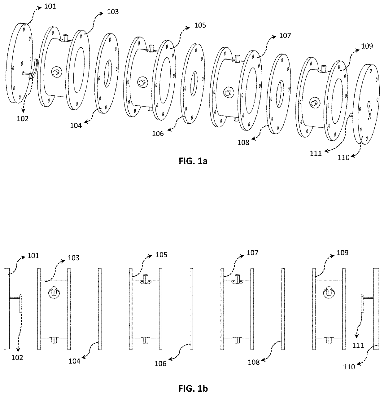
[0049]The next step is to realize the physical inter-resonator coupling and input / output coupling to match the above requirements. FIG. 1 depicts the drawings of the invention in exploded condition identifying different parts of the tunable co-axial filter. The isometric view is shown in FIG. 1a, whereas the side view is depicted in FIG. 1b. The inter-resonator couplings are realized using elliptic iris openings 104, 106 and 108. The input / output couplings are realized using circular-shaped probes 102 and 111 mounted on to SMA connectors. The elliptical casings (103, 105, 107 and 109) and end-plates (101 and 110) complete the filter housing. The fine tuning screws are mounted in the elliptical casings. The ball-bearing is placed on the end plates.

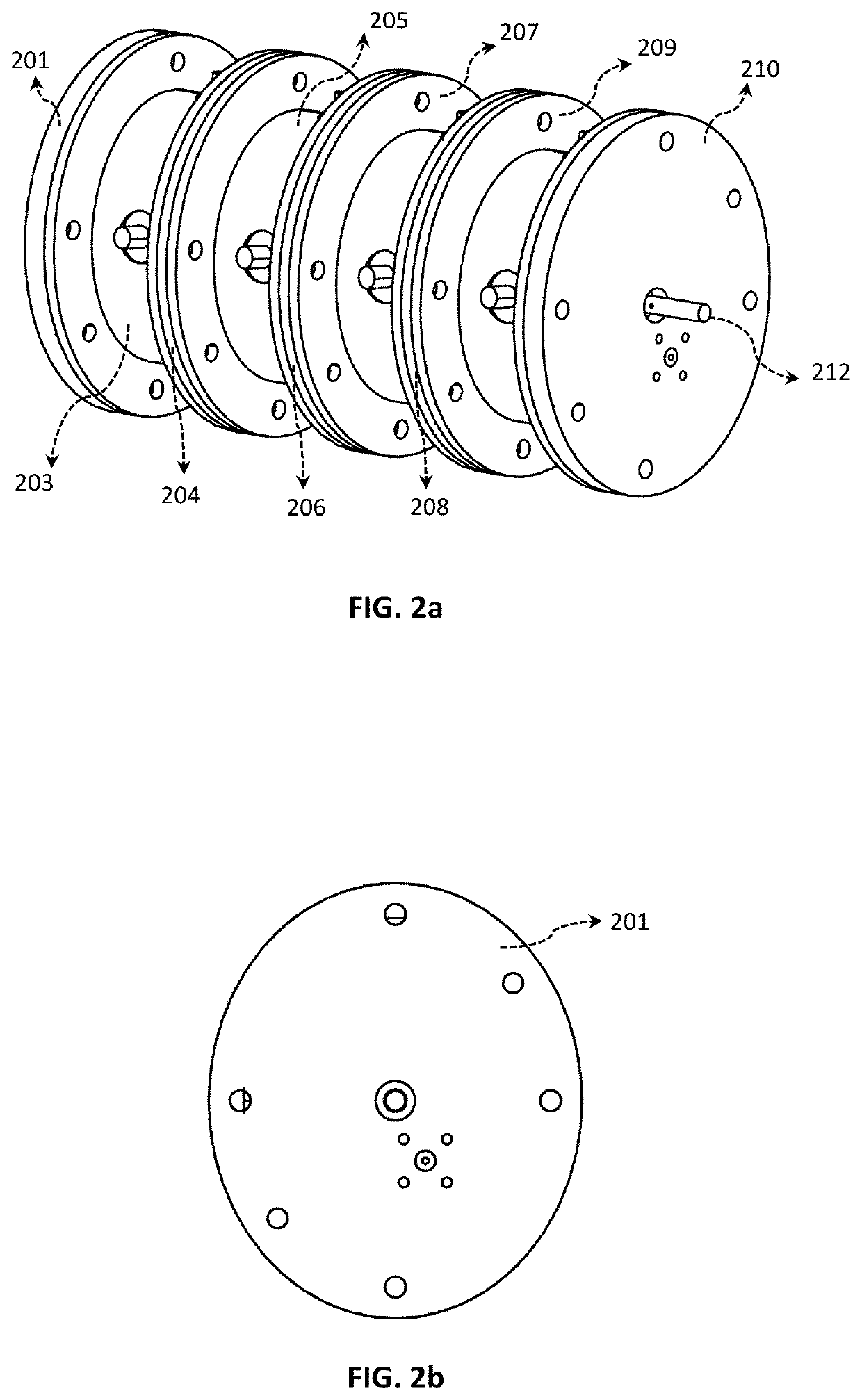
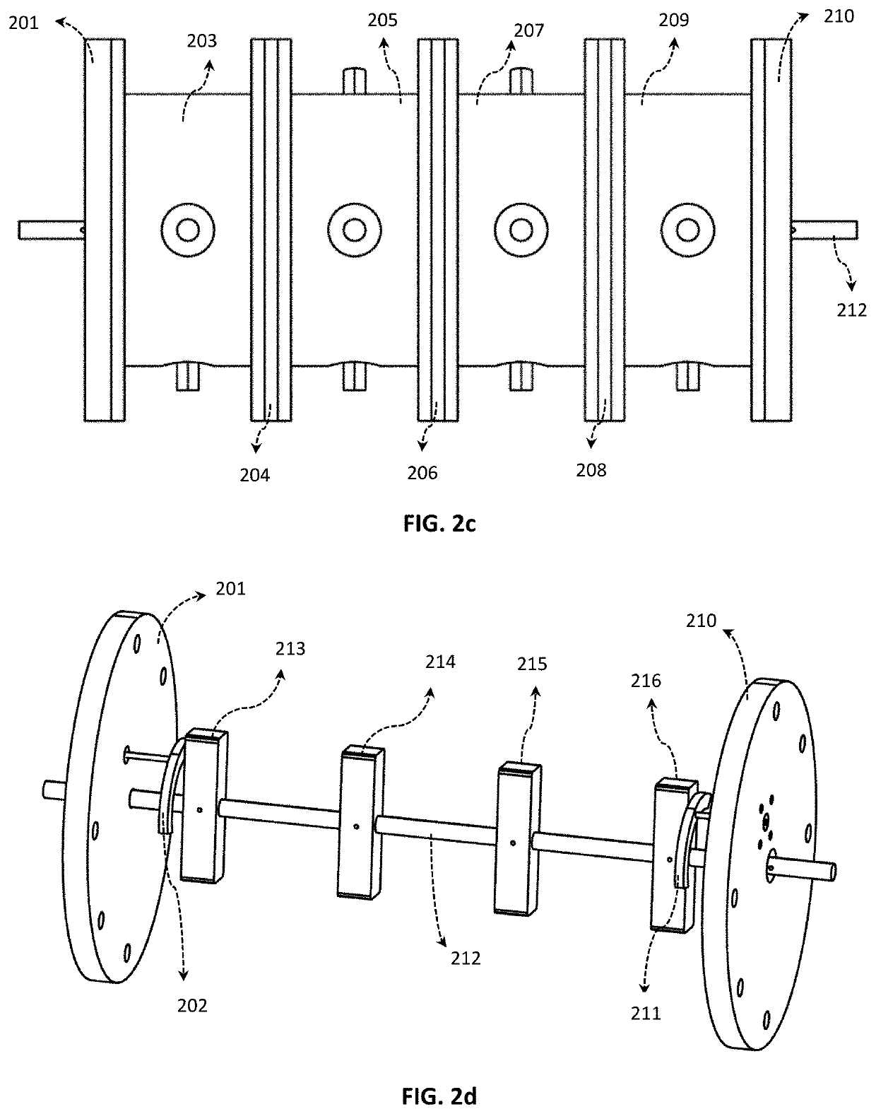
[0050]FIG. 2 depicts the drawings of the first embodiment of the invention in the assembled condition identifying different parts of the tunable co-axial filter. The isometric view is shown in FIGS. 2a. 201 and 210 identify the end plates o...

second embodiment

[0056]FIG. 8 depicts the schematic of the invention, where both center frequency and bandwidth of the filter can be tuned by rotating the tuning rods. Two filters 801 and 802 are cascaded. The output of one filter is connected to the input of the other filter using a cable 803. An isolator can also be used in-between the filters to improve the return loss performance. The tuning rods 804 and 805 can be rotated to tune the center frequency and bandwidth of the overall filter response.

third embodiment

[0057]FIG. 9 depicts the schematic of the invention, which is a diplexer using two filters. Two filters 901 and 902 are connected using a junction diplexing 903. The two filters are tuned either by one tuning rod or two separate tuning rods (904 and 905).


PUM


Abstract

The present invention is a high Q tunable co-axial filter, which maintains a constant absolute bandwidth and a constant Q over the tuning range. The present filter can be tuned by a single rotational mechanism irrespective of the filter order. A plurality of tunable resonators is aligned on a common filter axis. Each resonator has a casing having an inner wall and a cavity. The resonators are coupled by an iris opening. A pair of end plates completes the filter casing. A rotating rod placed on the common axis of the resonated, that has a tuning post attached to it, and each post located in each resonator, is used to tune the filter.

Description

FIELD OF INVENTION[0001]The present invention relates to the design and development of a tunable bandpass filter.DESCRIPTION OF BACKGROUND ART[0002]Tunable bandpass filter is one of the vital components of frequency reconfigurable (or frequency agile) wireless systems which facilitate effective utilization of allotted frequency spectrum. Furthermore, frequency reconfigurable wireless systems can be a cost effective solution for wireless base-stations as well as for satellite & aero-space applications. In satellite application, on orbit flexible payload (or programmable payload) is one such encouraging development on the horizon. These systems inevitably require high Q (Quality factor) tunable bandpass filters with a constant absolute bandwidth over the tuning range.[0003]One of the important requirements for tunable filters in most applications is to maintain constant absolute bandwidth over the tuning range. The data rate is bandwidth dependent thus maintaining the same date rate o...

Claims


Application Information

Patent Timeline
Patent Type & Authority Applications(United States)
IPC IPC(8): H01P1/205H01P1/208H01P1/202
CPCH01P1/202H01P1/2084H01P1/2056H01P1/2053H01P1/207
Inventor BASAVARAJAPPA, GOWRISHMANSOUR, RAAFAT R
Owner BASAVARAJAPPA GOWRISH
Why Eureka
Try Eureka