Tunable filter with minimum variations in absolute bandwidth and insertion loss using a single tuning element
a filter and tuning element technology, applied in the field of tunable bandpass filter, can solve the problems of high q (quality factor, inability to meet the bandwidth change, bulky and expensive), and achieve the effect of reducing the production cost of communication systems, constant absolute band, and wide tuning rang
- Summary
- Abstract
- Description
- Claims
- Application Information
AI Technical Summary
Benefits of technology
Problems solved by technology
Method used
Image
Examples
first embodiment
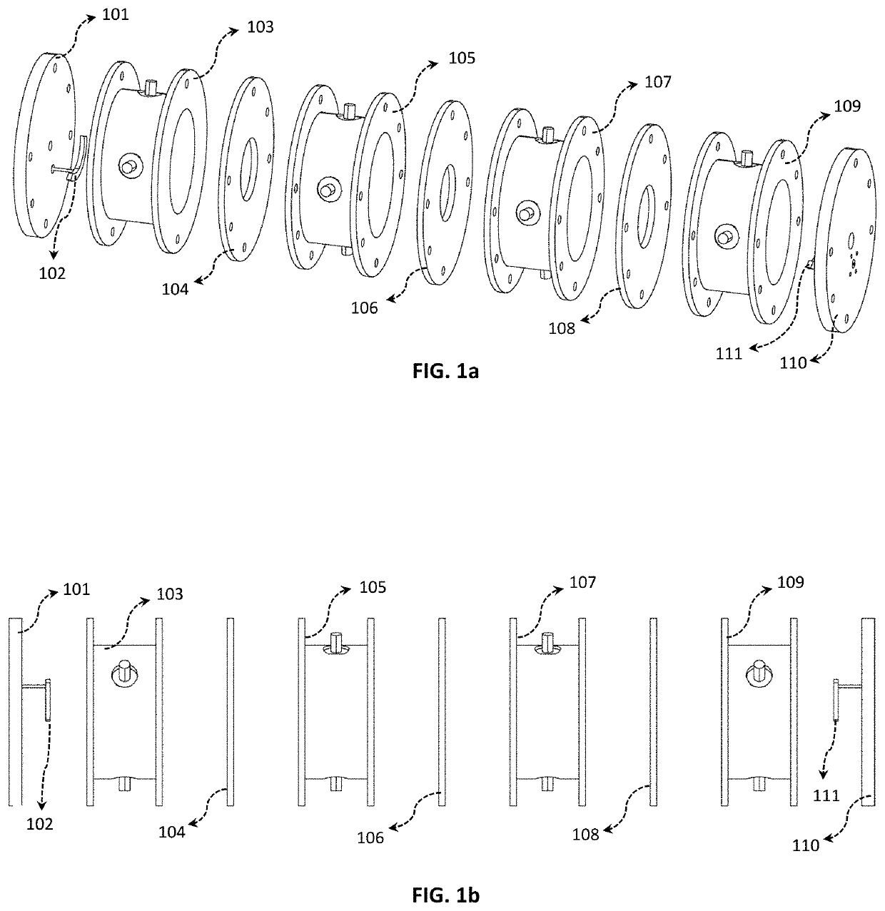
[0049]The next step is to realize the physical inter-resonator coupling and input / output coupling to match the above requirements. FIG. 1 depicts the drawings of the invention in exploded condition identifying different parts of the tunable co-axial filter. The isometric view is shown in FIG. 1a, whereas the side view is depicted in FIG. 1b. The inter-resonator couplings are realized using elliptic iris openings 104, 106 and 108. The input / output couplings are realized using circular-shaped probes 102 and 111 mounted on to SMA connectors. The elliptical casings (103, 105, 107 and 109) and end-plates (101 and 110) complete the filter housing. The fine tuning screws are mounted in the elliptical casings. The ball-bearing is placed on the end plates.
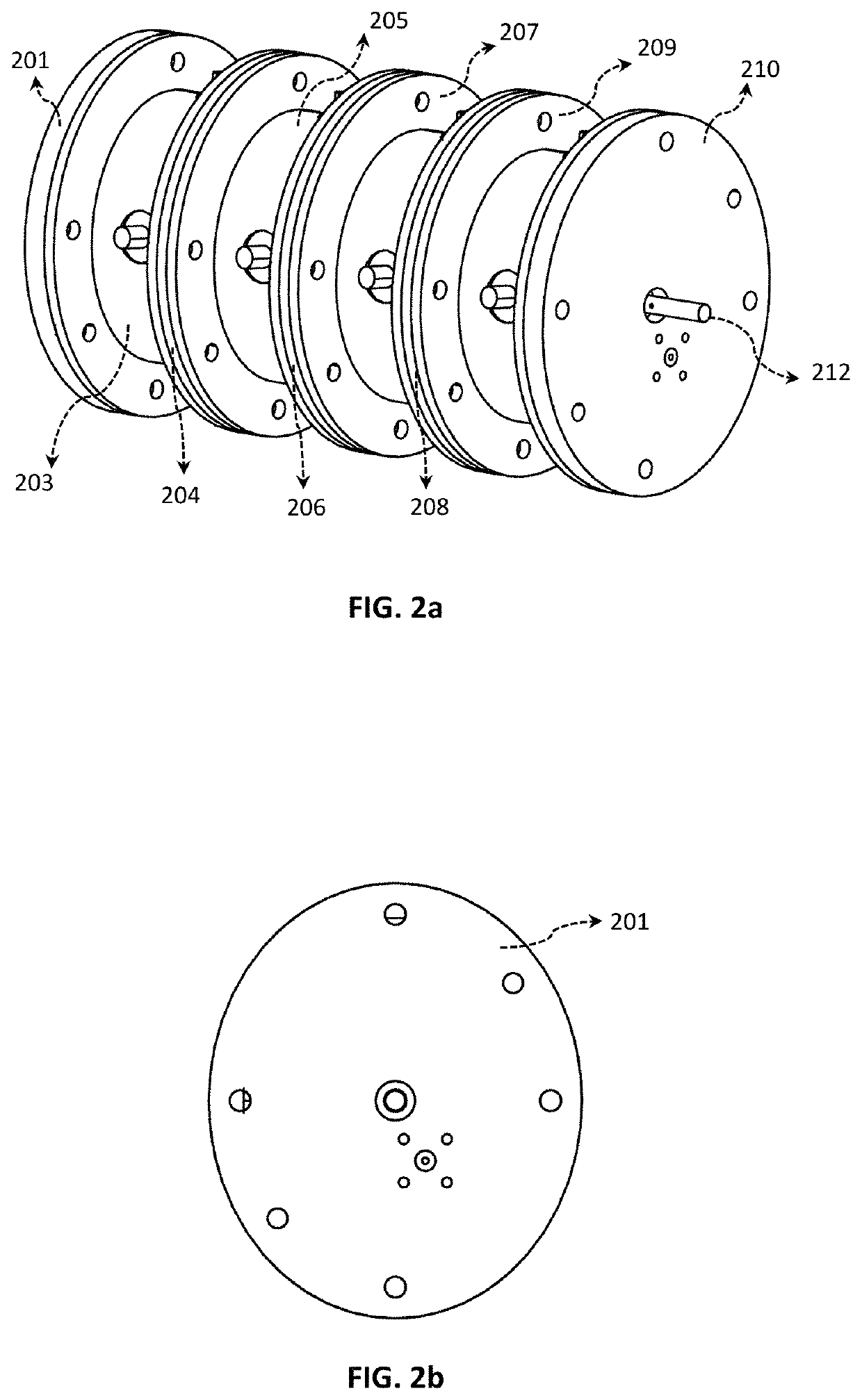
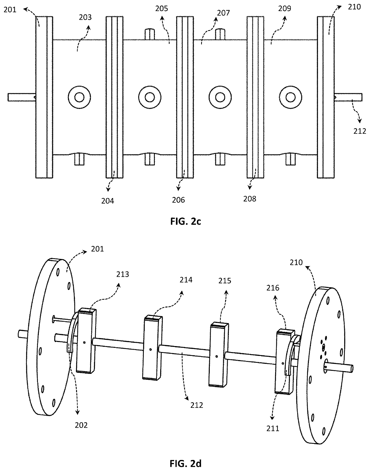
[0050]FIG. 2 depicts the drawings of the first embodiment of the invention in the assembled condition identifying different parts of the tunable co-axial filter. The isometric view is shown in FIG. 2a. 201 and 210 identify the end plates of...
second embodiment
[0056]FIG. 8 depicts the schematic of the invention, where both center frequency and bandwidth of the filter can be tuned by rotating the tuning rods. Two filters 801 and 802 are cascaded. The output of one filter is connected to the input of the other filter using a cable 803. An isolator can also be used in-between the filters to improve the return loss performance. The tuning rods 804 and 805 can be rotated to tune the center frequency and bandwidth of the overall filter response.
third embodiment
[0057]FIG. 9 depicts the schematic of the invention, which is a diplexer using two filters. Two filters 901 and 902 are connected using a junction diplexing 903. The two filters are tuned either by one tuning rod or two separate tuning rods (904 and 905).
PUM
 Abstract
Description
Claims
Application Information
 - R&D
- Intellectual Property
- Life Sciences
- Materials
- Tech Scout
- Unparalleled Data Quality
- Higher Quality Content
- 60% Fewer Hallucinations
Browse by: Latest US Patents, China's latest patents, Technical Efficacy Thesaurus, Application Domain, Technology Topic, Popular Technical Reports.
© 2025 PatSnap. All rights reserved.Legal|Privacy policy|Modern Slavery Act Transparency Statement|Sitemap|About US| Contact US: help@patsnap.com


