
Measurement System Utilizing a Frequency-Dithered Local Oscillator

a local oscillator and measurement system technology, applied in the field of instruments, can solve the problems of not easy to prototype the requisite topology using certain, discrete spurs to appear like white noise, and difficulty in spreading mixer input, etc., to achieve high-performance spectrum analysis, facilitate spreading mixer input, and new levels of performance

Active Publication Date: 2015-01-15
NATIONAL INSTRUMENTS
View PDF6 Cites 3 Cited by
  • Summary
  • Abstract
  • Description
  • Claims
  • Application Information

AI Technical Summary

Benefits of technology

A VSA (vector signal analyzer) has been developed that uses a novel circuit topology and signal processing to spread the energy from spurs in a receiver over a wider frequency range. This results in the spurs appearing like white noise, which allows the receiver system to handle lower levels of signals. This technique can transform inexpensive hardware into a high performance spectrum analysis solution. It can also be used for signal generation to improve the performance of signal generators for certain applications. The spur reduction technique described herein works well against CW or narrow band spurs and can provide substantial spur reduction even when the spectrum can be widely spread compared to the final resolution BW of the measurement. A combination of averaging and a dithered LO can also improve EVM measurements.

Problems solved by technology

This results in causing discrete spurs to appear like white noise.
While it may appear excessive to use a VSG simply to generate a frequency agile LO signal, it is not difficult to prototype the requisite topology using certain already available tools, such as the National Instruments NI-5791 RF FAM (FlexRIO Adapter Module) for example.
The delay may include the delay in the DAC reconstruction filters, the delay in the ADC anti-alias filters, and the electrical delay in the line length between the modulator output and the demodulator LO port.

Method used


Image

  • Measurement System Utilizing a Frequency-Dithered Local Oscillator
  • Measurement System Utilizing a Frequency-Dithered Local Oscillator
  • Measurement System Utilizing a Frequency-Dithered Local Oscillator

Examples


Embodiment Construction

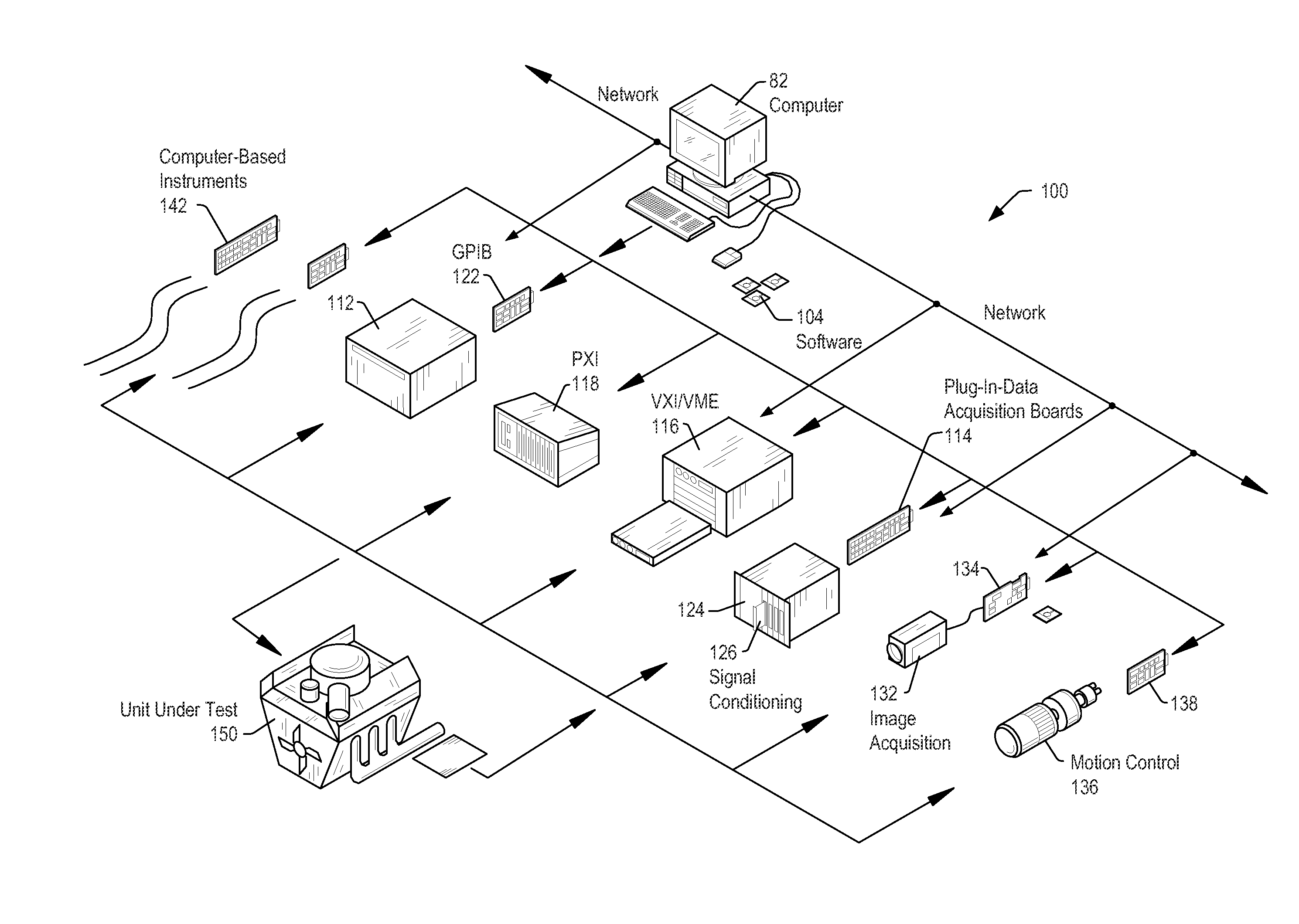
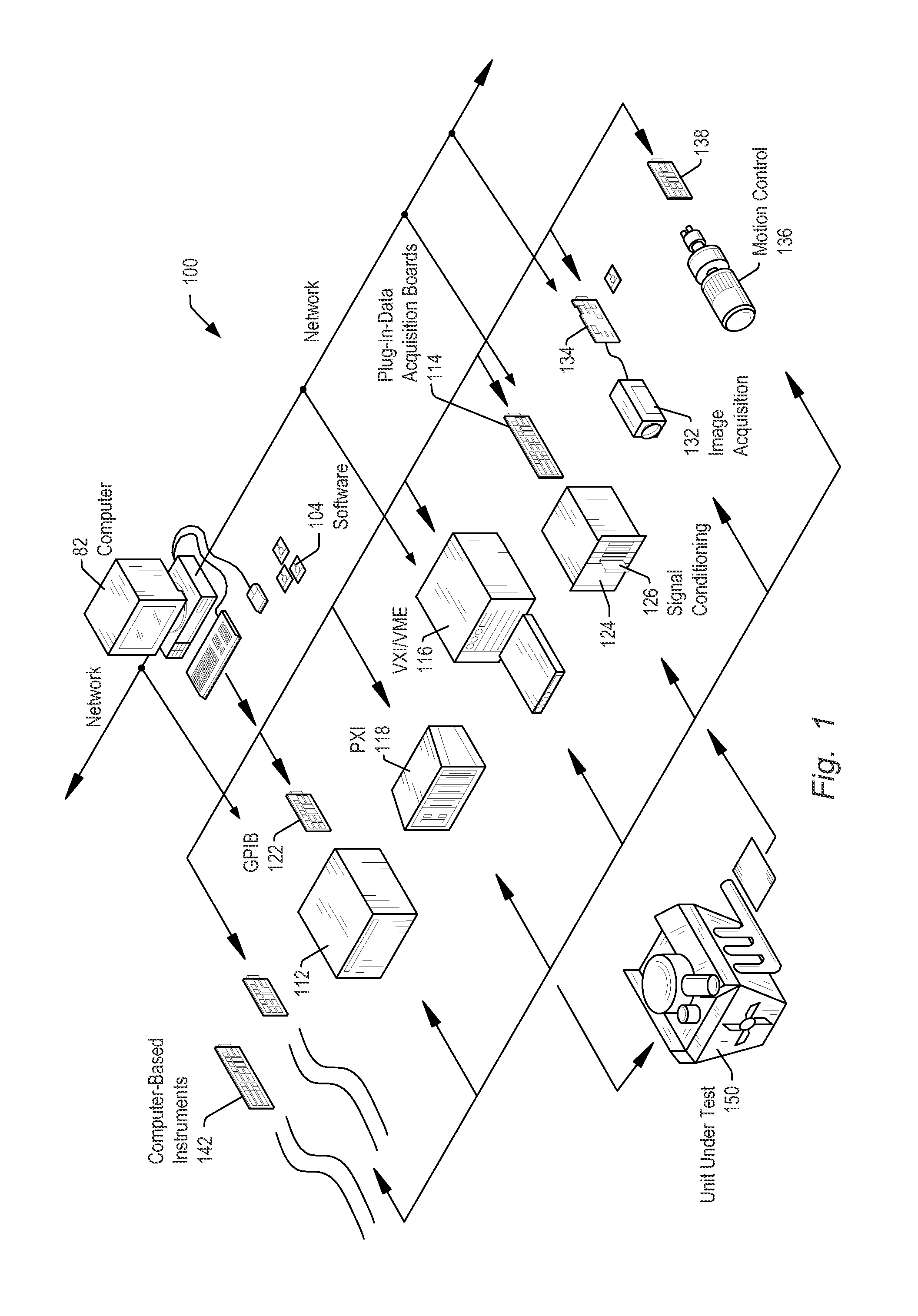
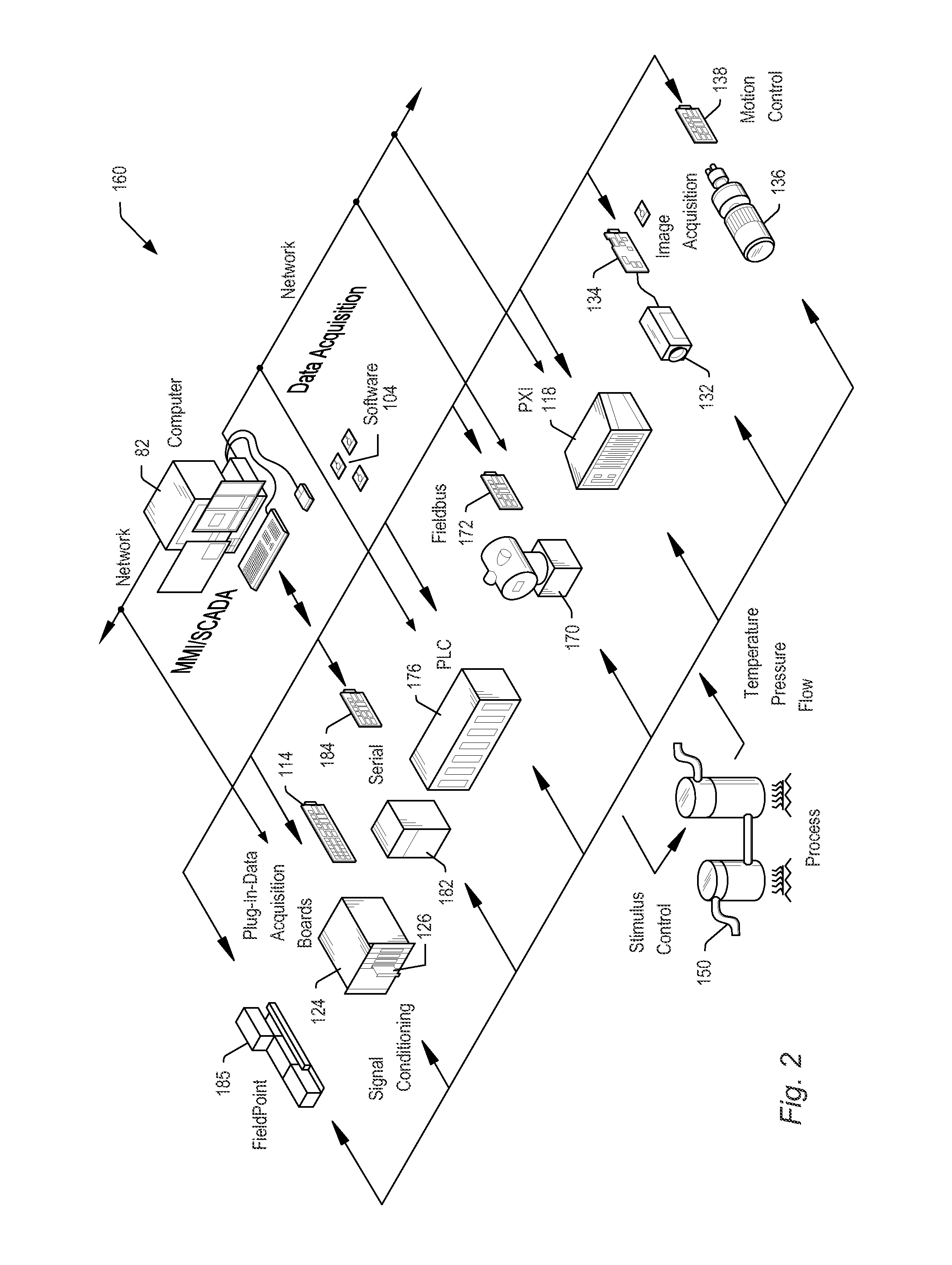
[0022]Embodiments of the present invention may be used in systems configured to perform test and / or measurement functions, to control and / or model instrumentation or industrial automation hardware, or to model and simulate functions, e.g., modeling or simulating a device or product being developed or tested, etc. More specifically, it may be used in various instances where input protection for instrumentation equipment is required, without degrading the performance of the protected instrumentation equipment. However, it is noted that the present invention may equally be used for a variety of applications, and is not limited to the applications enumerated above. In other words, applications discussed in the present description are exemplary only, and the present invention may be used in any of various types of systems. Thus, the system and method of the present invention may be used in any number of different applications. It is noted that the various terms or designations for circui...


PUM


Abstract

An improved receiver system may include an input to receive an input signal, and a signal generating circuit to generate a desired oscillator signal that is a single sideband radio frequency signal of time varying frequency. The receiver may also include a downconversion stage to generate an intermediate frequency (IF) signal based on the input signal and the desired oscillator signal. A signal processing block in the receiver may be used to produce an output signal based on the IF signal by frequency shifting the IF signal by an amount that compensates for the time varying frequency of the desired oscillator signal. The desired oscillator signal may be generated using a vector signal generator that receives a control value from the signal processing block, converts the control value to a pair of analog input signals, and generates the desired oscillator signal by quadrature modulating the pair of analog input signals.

Description

FIELD OF THE INVENTION[0001]The present invention relates to the field of instrumentation, and more particularly to using a dithered local oscillator when making narrow resolution bandwidth vector signal analyzer measurements.DESCRIPTION OF THE RELATED ART[0002]In many industrial applications (and others), instruments collect data or information from an environment or unit under test (UUT), and may also analyze and process acquired data. Some instruments provide test stimuli to a UUT. Examples of instruments include oscilloscopes, digital multimeters, pressure sensors, arbitrary waveform generators, digital waveform generators, etc. The information that may be collected by respective instruments includes information describing voltage, resistance, distance, velocity, pressure, oscillation frequency, humidity, and / or temperature, among others. Computer-based instrumentation systems typically include transducers for capturing a physical phenomenon and generating a representative elect...

Claims


Application Information

Patent Timeline
Patent Type & Authority Applications(United States)
IPC IPC(8): G01R23/16H03B28/00
CPCG01R23/16H03B28/00G01R27/28
Inventor WERTZ, DANIEL S.
Owner NATIONAL INSTRUMENTS
Learn More