High-pressure tank manufacturing method

Active Publication Date: 2020-07-23
TOYOTA JIDOSHA KK
View PDF0 Cites 0 Cited by
  • Summary
  • Abstract
  • Description
  • Claims
  • Application Information

AI Technical Summary

Benefits of technology

The present invention provides a high-pressure tank manufacturing method that improves productivity compared to conventional methods. The method involves heating a resin liner using a conductive heating material placed on the outer periphery of the liner, which ensures uniform heating of the resin impregnated in both deep and superficial layers of the liner. Additionally, the method simplifies the manufacturing steps and shortens the hardening time of the resin, resulting in a faster manufacturing period and improved productivity of the high-pressure tank.

Problems solved by technology

Accordingly, although the excellent effect, ensuring suppressing the increase of Vf of the fiber-reinforced resin layer, is exhibited, a problem remains in shorting of a hardening time of the entire thermosetting resin.
Accordingly, the conventional method for manufacturing the composite article needs to take out the material in the heat conductive relationship with the inner surface of the liner after the phase c. of hardening the composite article, causing problems of complicated manufacturing process and requiring time.

Method used


Image

  • High-pressure tank manufacturing method
  • High-pressure tank manufacturing method
  • High-pressure tank manufacturing method

Examples


Embodiment Construction

[0022]The following describes embodiments of a high-pressure tank manufacturing method according to the present disclosure with reference to the drawings.

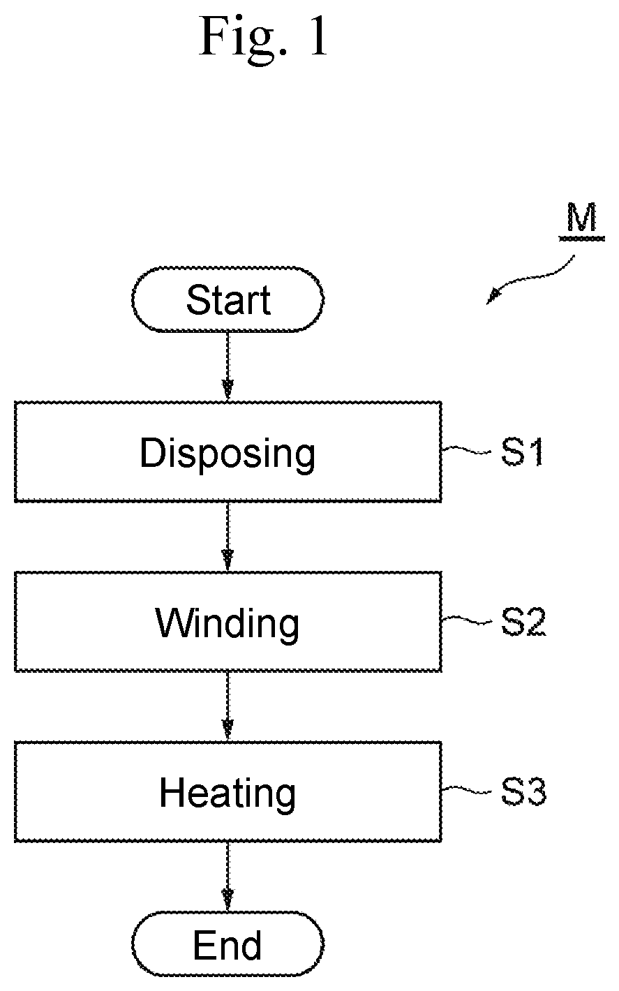
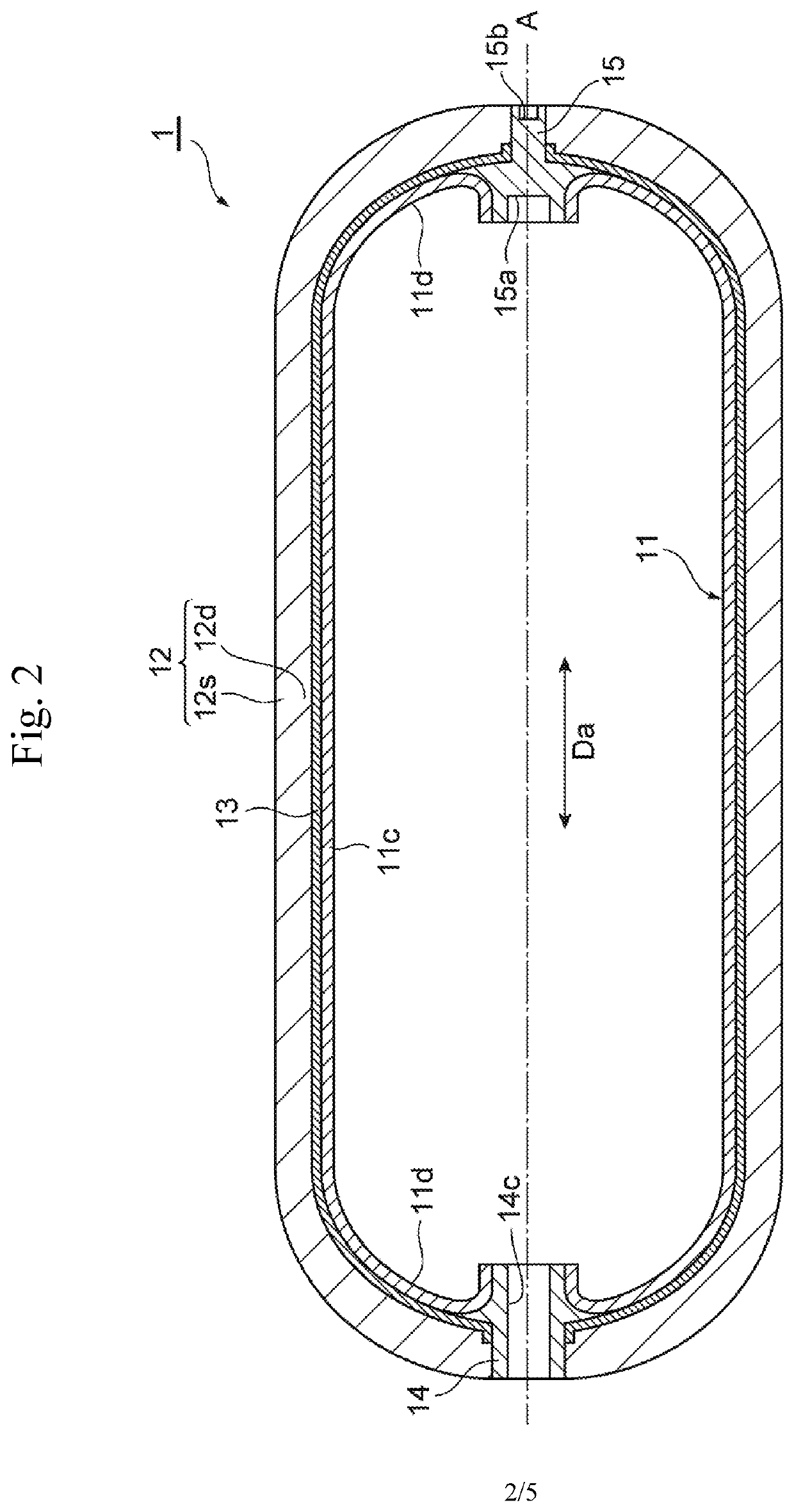
[0023]FIG. 1 is a flowchart illustrating each step of a high-pressure tank manufacturing method M according to one embodiment of the present disclosure. FIG. 2 is a schematic cross-sectional view illustrating an example of a configuration of a high-pressure tank 1 produced by the high-pressure tank manufacturing method M illustrated in FIG. 1.

[0024]The high-pressure tank manufacturing method M according to this embodiment is a manufacturing method for a high-pressure gas tank that stores a high-pressure gas, for example, around 35 [MPa] or 70 [MPa]. Specifically, the high-pressure tank 1 is, for example, a container that stores a high-pressure hydrogen gas as described above. More specifically, the high-pressure tank 1 is, for example, a high-pressure tank for vehicle mounted to a fuel cell vehicle to supply a fuel cell stack, whic...


PUM

PropertyMeasurementUnit
Pressureaaaaaaaaaa
Electrical conductoraaaaaaaaaa
Electrical resistivityaaaaaaaaaa

Abstract

There is provided a high-pressure tank manufacturing method that ensures a shorten heating period compared with a conventional one and eliminates a need for taking out a material for heating after heating. A high-pressure tank manufacturing method includes: disposing a conductive heating material on an outer periphery of a resin liner; winding a conductive fiber with which thermosetting resin is impregnated around the outer periphery of the resin liner on which the heating material is disposed; and heating the heating material and the fiber on the outer periphery of the resin liner by induction heating to harden the thermosetting resin.

Description

CROSS REFERENCE TO RELATED APPLICATIONS[0001]The present application claims priority from Japanese patent application JP 2019-007557 filed on Jan. 21, 2019, the entire content of which is hereby incorporated by reference into this application.BACKGROUNDTechnical Field[0002]The present disclosure relates to a high-pressure tank manufacturing method.[0003]Background Art[0004]There has been conventionally known a disclosure regarding an induction heating method and its device that perform high-frequency induction heating on a heated object with induction heating coils and a high-pressure gas tank manufacturing method (see JP 2013-163305 A). An object of the conventional disclosure is to provide a new induction heating method that suppresses increase of fiber volume content percentage (increased Vf) of a fiber-reinforced resin layer formed by winding a fiber impregnated with thermosetting resin (see the paragraph 0006 to the paragraph 0008 in the literature). JP 2013-163305 A discloses ...

Claims


Application Information

Patent Timeline
IPC IPC(8): B29C53/60B29C70/30
CPCB29C70/30F17C2203/0621F17C2201/0109F17C2203/0668F17C2203/0646F17C2209/2154B29C53/602B29C70/382B29C70/20B29C35/0805B29C2035/0811B29L2031/7156B29K2995/0005B29C53/845B29C53/582B29C53/005B29C70/882B29C70/885
Inventor USUI, TAKASHI
Owner TOYOTA JIDOSHA KK
Why Eureka
Try Eureka