Radio-frequency heating apparatus and radio-frequency heating method

Active Publication Date: 2016-07-19
PANASONIC INTELLECTUAL PROPERTY MANAGEMENT CO LTD
View PDF55 Cites 16 Cited by
  • Summary
  • Abstract
  • Description
  • Claims
  • Application Information

AI Technical Summary

Benefits of technology

[0016]With this configuration, radio-frequency power is radiated from a plurality of antennas with an appropriate phase difference based on the geometry information of an object acquired by the geometry information acquisition unit. Consequently, a distribution of intensity of an electromagnetic field composed of a standing wave, which is suitable to the geometry of the object may be formed in the heating chamber, and thus the object may be efficiently and uniformly heated in accordance with the geometry of the object.
[0017]In the case where the plurality of radio-frequency waves radiated from a plurality of antennas are in phase, the distribution of the intensity of the electromagnetic field in the heating chamber has the same intensity area extending in the direction parallel to the same plane on which a plurality of

Problems solved by technology

This configuration causes the apparatus to increase in size and cost.
In addition, because of the employed mechanical drive, the location of each antenna is unstable and the probability of failure tends to increase.
That is to say, the region where the object exists is not heated in

Method used


Image

  • Radio-frequency heating apparatus and radio-frequency heating method
  • Radio-frequency heating apparatus and radio-frequency heating method
  • Radio-frequency heating apparatus and radio-frequency heating method

Examples


Example

[Embodiment 1]

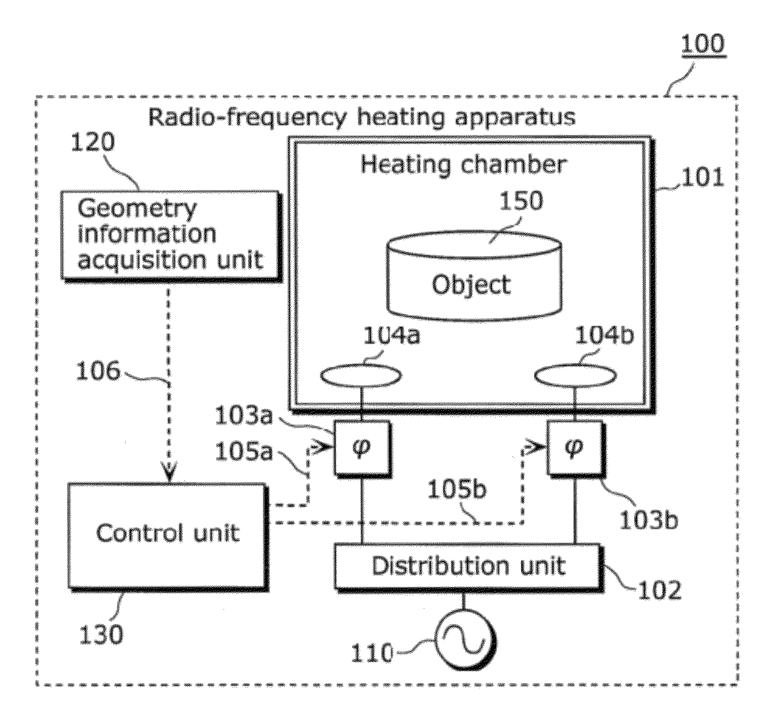
[0066]A radio-frequency heating apparatus according to Embodiment 1 of the present invention is a radio-frequency heating apparatus for heating an object placed in a heating chamber, and includes: a radio-frequency power generation unit configured to generate radio-frequency power; a phase varying unit configured to vary a in phase of radio-frequency power generated by the radio-frequency power generation unit; a plurality of antennas which are placed on a same plane in the heating chamber and radiate a plurality of radio-frequency waves to the object, the radio-frequency waves having a predetermined phase difference caused by phase variation in the phase varying unit; a geometry information acquisition unit configured to acquire geometry information indicating a geometry of the object; and a control unit configured to control the phase varying unit so that the radio-frequency waves are in phase in a first mode, and configured to control the phase varying unit so that ...

Example

[Embodiment 2]

[0176]Hereinafter, Embodiment 2 of the present invention is described.

[0177]The radio-frequency heating apparatus according to the present embodiment is different from the radio-frequency heating apparatus 100 according to Embodiment 1 in that the geometry information of an object is obtained by user operation. That is to say, the radio-frequency heating apparatus 100 according to Embodiment 1 does not need user operation, for example, geometry information of the object is acquired by an infrared sensor or a laser sensor. On the other hand, the radio-frequency heating apparatus according to the present embodiment does not need a two-dimensional sensors or a three-dimensional sensors such as an infrared sensor or a laser sensor, and acquires the geometry information of the object by user operation.

[0178]FIG. 17 is a block diagram showing the basic configuration of a radio-frequency heating apparatus according to Embodiment 2.

[0179]The radio-frequency heating apparatus s...

Example

[Embodiment 3]

[0192]Hereinafter, Embodiment 3 of the present invention is described.

[0193]The radio-frequency heating apparatus according to the present embodiment is different from the radio-frequency heating apparatus 100 according to Embodiment 1 and the radio-frequency heating apparatus 200 according to Embodiment 2 in that the in-phase mode and the opposite-phase mode are switched from each other independently of geometry information. That is to say, Embodiment 1 and Embodiment 2 have a configuration in which the geometry information of the object is acquired, and then the in-phase mode and the opposite-phase mode are switched from each other based on the acquired geometry information, however, the present embodiment has a configuration in which the in-phase mode and the opposite-phase mode are always alternately switched from each other.

[0194]With the present embodiment, an infrared sensor, a geometry selection button operated by a user, and the like are not needed. In additio...


PUM


Abstract

A radio-frequency heating apparatus includes a phase varying unit to vary the phase of radio-frequency power; and a plurality of antennas which are placed on the same plane in a heating chamber and radiate a plurality of radio-frequency waves. The radio-frequency waves have a predetermined phase difference caused by phase variation in the phase varying unit. A geometry information acquisition unit acquires the geometry of an object; and a control unit controls the phase varying unit so that the radio-frequency waves are in phase in a first mode, and the radio-frequency waves are in opposite phase in a second mode. The control unit switches between the first mode and the second mode based on the acquired geometry information.

Description

BACKGROUND OF INVENTION[0001]1. Technical Field[0002]The present invention relates to a radio-frequency heating apparatus and a radio-frequency heating method for heating an object placed in a heating chamber.[0003]2. Background Art[0004]Conventionally, in order to improve heating efficiency and eliminate uneven heating and provide uniform heating for a radio-frequency heating apparatus which heats an object such as food using radio-frequency power, various techniques have been disclosed for providing local heating based on the state and geometry of the object, and for stirring radiated radio-frequency power in a heating chamber.[0005]For example, Patent Literature 1 discloses a microwave oven which has a radiation antenna on the outer periphery of an emission antenna. In the microwave oven, by rotating an emission antenna, a state in which the emission antenna is radio-frequency coupled with the radiation antenna, and a state in which the emission antenna is not radio-frequency cou...

Claims


Application Information

Patent Timeline
IPC IPC(8): H05B6/04H05B6/72H05B6/70H05B6/64
CPCH05B6/6447H05B6/70H05B6/705H05B6/72Y02B40/146Y02B40/00
Inventor OKAJIMA, TOSHIYUKI
Owner PANASONIC INTELLECTUAL PROPERTY MANAGEMENT CO LTD
Why Eureka
Try Eureka