Optical security element

Active Publication Date: 2020-07-23
SICPA HLDG SA
View PDF0 Cites 0 Cited by
  • Summary
  • Abstract
  • Description
  • Claims
  • Application Information

AI Technical Summary

Benefits of technology

[0011]It is a further object of this invention to provide an efficient method to select a target visual effect which is compatible with the above-mentioned reduced size(s).
[0012]According to one aspect the invention relates to an optical security element comprising a reflective light-redirecting surface, or refractive transparent or partially transparent light-redirecting surface, having a relief pattern operable to redirect incident light from a light source and form a projected image on a projection surface, the optical parameters of this optical security element fulfilling a specific projection criterion such that the projected image comprises a caustic pattern reproducing a reference pattern that is easily recognizable by a person, using no further means (i.e. with naked eye) or common and easily available means, so that an object marked with this optical security element can be readily authenticated visually by the person. A reduced thickness of the relief pattern of optical security element makes it particularly suitable for marking objects of reduced dimensions like banknotes or security documents (e.g. identity papers, passports, cards, etc.) for example. The transparent aspect of the refractive optical security element makes it particularly suitable for marking at least partially transparent substrates (e.g. glass or plastic bottles, bottle caps, watch glasses, jewelry, gems, etc.)
[0013]In view of the great difficulty to determine reference patterns that can be conveniently reproduced by a projecte

Problems solved by technology

However, when the object is transparent, or partially transparent, these features may not be appropriate.
Most existing security features of security elements for documents, banknotes, secured tickets, passports, etc. have not been specifically developed for transparent objects/areas and, as such, are not well-suited for such an application.
Other features, for example, those obtained with invisible and fluorescent inks require specific excitation tools and/or d

Method used


Image

  • Optical security element
  • Optical security element
  • Optical security element

Examples


Example

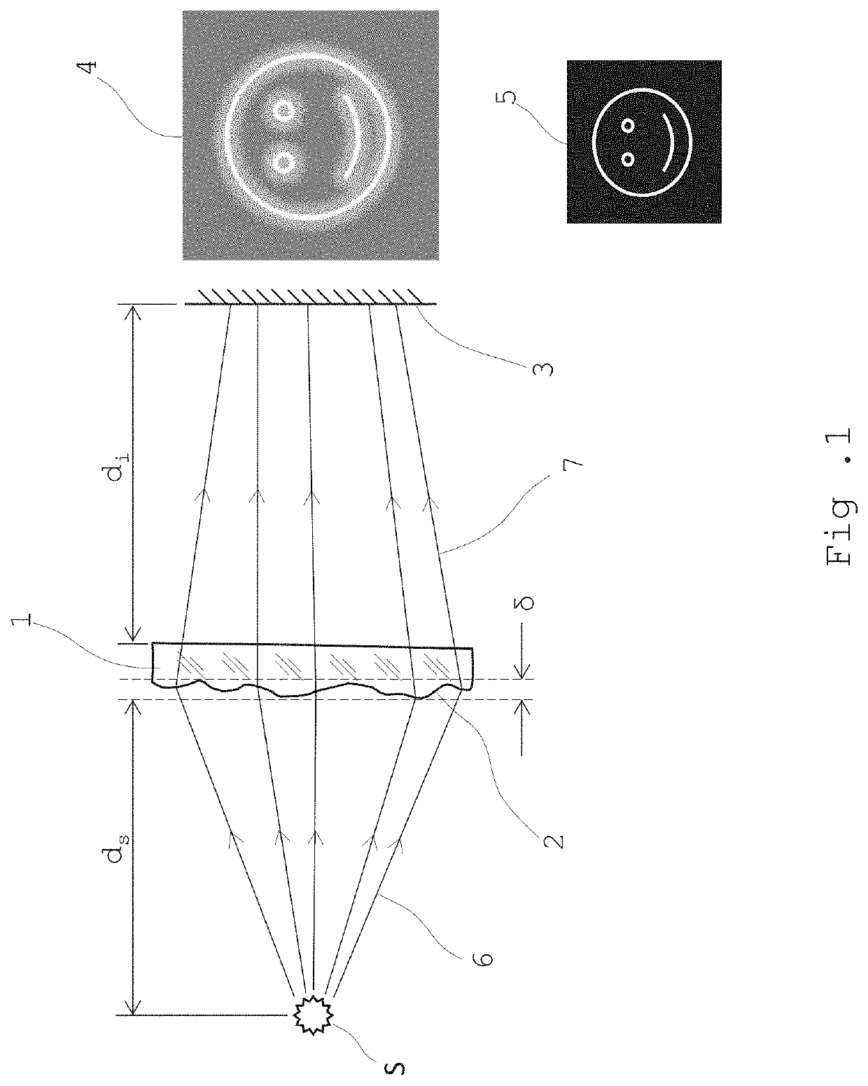
[0038]In optics, the term “caustic” refers to an envelope of light rays reflected or refracted by one or more surfaces, at least one of which is curved, as well as to projection of such light rays onto another surface. More specifically, a caustic is the curve or surface tangent to each light ray, defining a boundary of an envelope of rays as a curve of concentrated light. For example, the light pattern formed by sunrays at the bottom of a pool is a caustic “image” or pattern formed by a single light redirecting surface (the wavy air-water interface), whereas light passing through the curved surface of a water glass creates a cusp-like pattern on a table which the water glass is resting as it crosses two or more surfaces (e.g. air-glass, glass-water, air-water . . . ) which redirect its path.

[0039]In the following, the most common configuration where the (refractive) optical (security) element is bound by one curved surface and one flat surface will be used as an example, without re...


PUM


Abstract

The invention relates to a thin optical security element comprising a reflective or refractive light-redirecting surface having a relief pattern operable to redirect incident light from a light source and form a projected image on a projection surface, the optical parameters of this optical security element fulfilling a specific projection criterion such that the projected image comprises a caustic pattern reproducing a reference pattern that is easily visually recognizable by a person. The invention also relates to a method for designing a relief pattern of an optical security element.

Description

TECHNICAL FIELD[0001]The present invention relates to the technical field of reflective or refractive optical security elements operable to project caustic patterns upon appropriate illumination, and method for designing such optical security elements.BACKGROUND ART[0002]There is a need for security features on objects, that can be authenticated by the so-called “person in the street”, using commonly available means. These means include using the five senses—mostly, sight and touch—plus using widespread tools, such as for example a mobile phone.[0003]Some common examples of security features are forensic fibers, threads or foils (incorporated into a substrate like paper for example), watermarks, intaglio printing or microprinting (possibly printed on a substrate with optically variable inks) which can be found on banknotes, credit cards, ID's, tickets, certificates, documents, passports etc. These security features can include optically variable inks, invisible inks or luminescent i...

Claims


Application Information

Patent Timeline
IPC IPC(8): B42D25/324B42D25/435B42D25/44
CPCB42D25/44B42D25/435B42D25/324B42D25/351G02B5/1847G02B5/1866G02B5/1861G02B5/1842
Inventor CALLEGARI, ANDREADEGOTT, PIERREDINOEV, TODORGARNIER, CHRISTOPHEMAYER, ALAINSCHWARTZBURG, YULIYTESTUZ, ROMAINPAULY, MARK
Owner SICPA HLDG SA
Why Eureka
Try Eureka