
Chlorine dioxide gas generating method, liquid composition, gel composition, and chlorine dioxide gas generating kit

a chlorine dioxide gas and generating method technology, applied in the field of chlorine dioxide gas generating method, liquid composition, gel composition, chlorine dioxide gas generating kit, can solve the problems of not being able to achieve the effect of immediately, not being able to sufficiently adjust the gas amount, and not being able to suppress an abrupt increase in chlorine dioxide gas concentration

Inactive Publication Date: 2020-07-23
CLO2 LAB INC
View PDF1 Cites 5 Cited by
  • Summary
  • Abstract
  • Description
  • Claims
  • Application Information

AI Technical Summary

Benefits of technology

The patent text describes a method for generating chlorine dioxide gas by mixing two agents, an activator and an activation inhibitor. The activator causes the gas to be generated immediately upon mixing, while the activation inhibitor slows down the reaction to prevent a sudden increase in gas concentration. The gas is generated stably for a long period of time by adjusting the amount of activation inhibitor added. The method also prevents air and moisture from contaminating the agents, allowing for long-term storage and easy mixing when used. The portability of the method is excellent, with the two agents stored in separate containers that can be mixed easily by breaking the first container.

Problems solved by technology

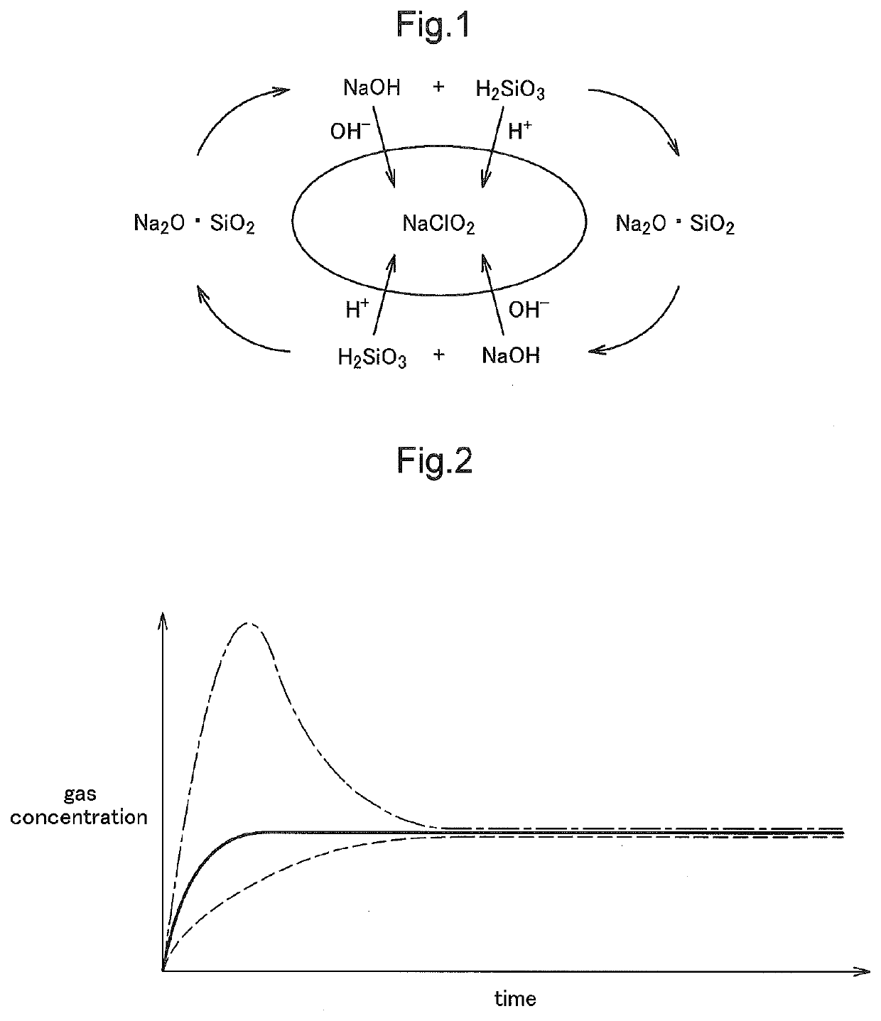
However, it is not possible to sufficiently adjust the amount of gas generated merely through the physical adsorbing action, and it is not possible to sufficiently suppress an abrupt increase in the chlorine dioxide gas concentration after an activator is added to the aqueous chlorite solution.
If a weak acid is used as the activator, an abrupt increase in the chlorine dioxide gas concentration can be suppressed, but there is a problem in that the effect cannot be immediately achieved because it requires time to reach the maximum concentration.
Furthermore, the concentration of generated chlorine dioxide gas depends only on the concentration of chlorite, and control of the maximum concentration is not possible.

Method used


Image

  • Chlorine dioxide gas generating method, liquid composition, gel composition, and chlorine dioxide gas generating kit
  • Chlorine dioxide gas generating method, liquid composition, gel composition, and chlorine dioxide gas generating kit
  • Chlorine dioxide gas generating method, liquid composition, gel composition, and chlorine dioxide gas generating kit

Examples


first embodiment

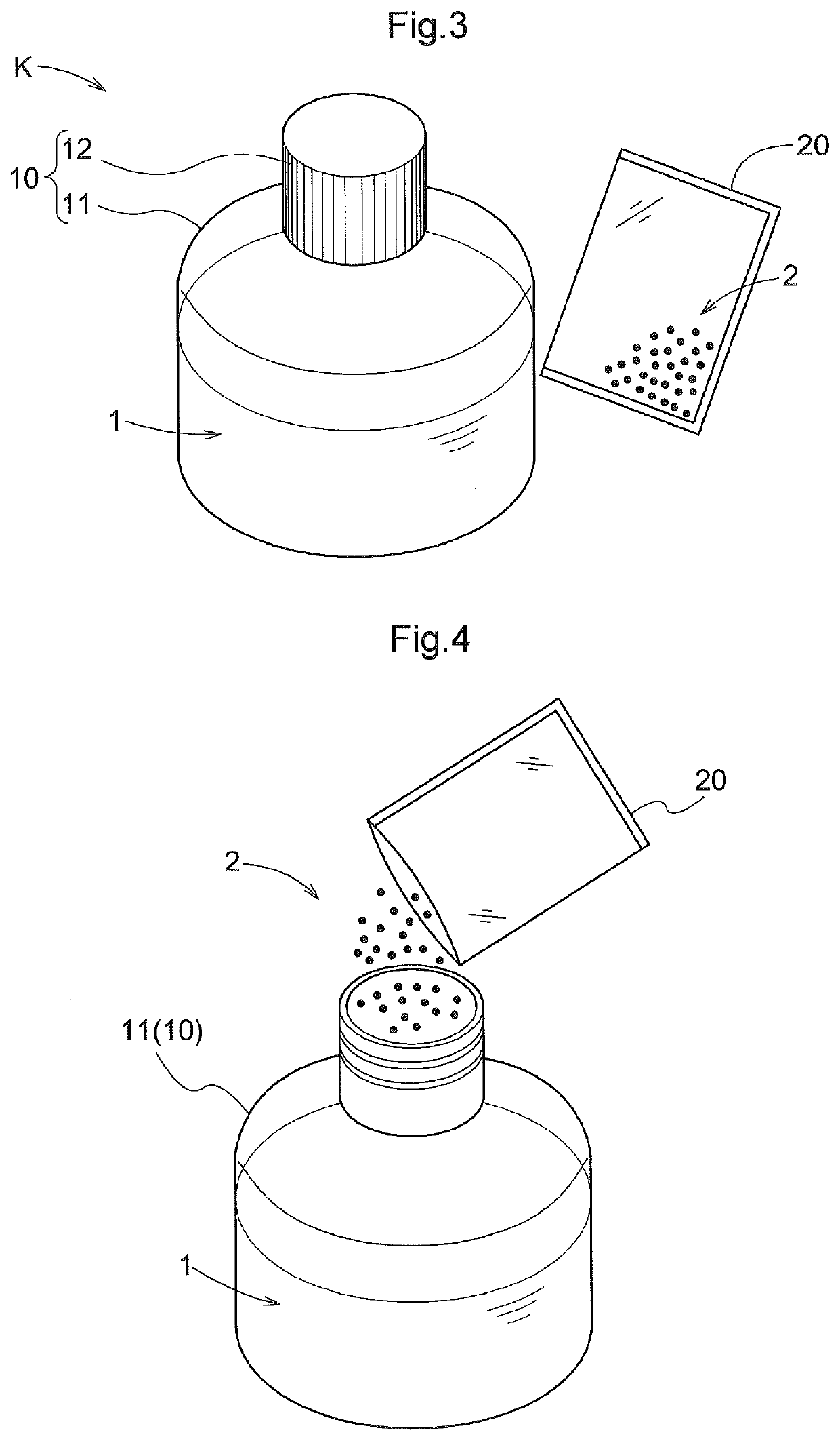
[0057]Hereinafter, a chlorine dioxide gas generating method, a liquid composition, a gel composition, and a chlorine dioxide gas generating kit according to a first embodiment will be described. The chlorine dioxide gas generating method of this embodiment is a method for immediately generating chlorine dioxide gas at a stable concentration, by mixing an aqueous chlorite solution, a fast-acting activator, a metal iodide, a slow-acting activation inhibitor, and, optionally, an absorbent resin. In this embodiment, this method is performed using a chlorine dioxide gas generating kit K (see FIG. 3) including a first agent 1 containing an aqueous chlorite solution, a metal iodide, and a slow-acting activation inhibitor, and a second agent 2 containing a fast-acting activator, and, optionally, an absorbent resin. It is possible to immediately generate chlorine dioxide gas at a stable concentration, from a liquid composition or a gel composition 3 (see FIG. 5) obtained by mixing the first ...

second embodiment

[0093]Hereinafter, a chlorine dioxide gas generating method, a liquid composition, a gel composition, and a chlorine dioxide gas generating kit according to a second embodiment will be described. In this embodiment, the aqueous chlorite solution, the fast-acting activator, the metal iodide, the slow-acting activation inhibitor, and the absorbent resin are allocated to the first agent 1 and the second agent 2 of the chlorine dioxide gas generating kit K in a manner different from that of the first embodiment. Furthermore, the specific configuration of the container of the chlorine dioxide gas generating kit K is different from that of the first embodiment.

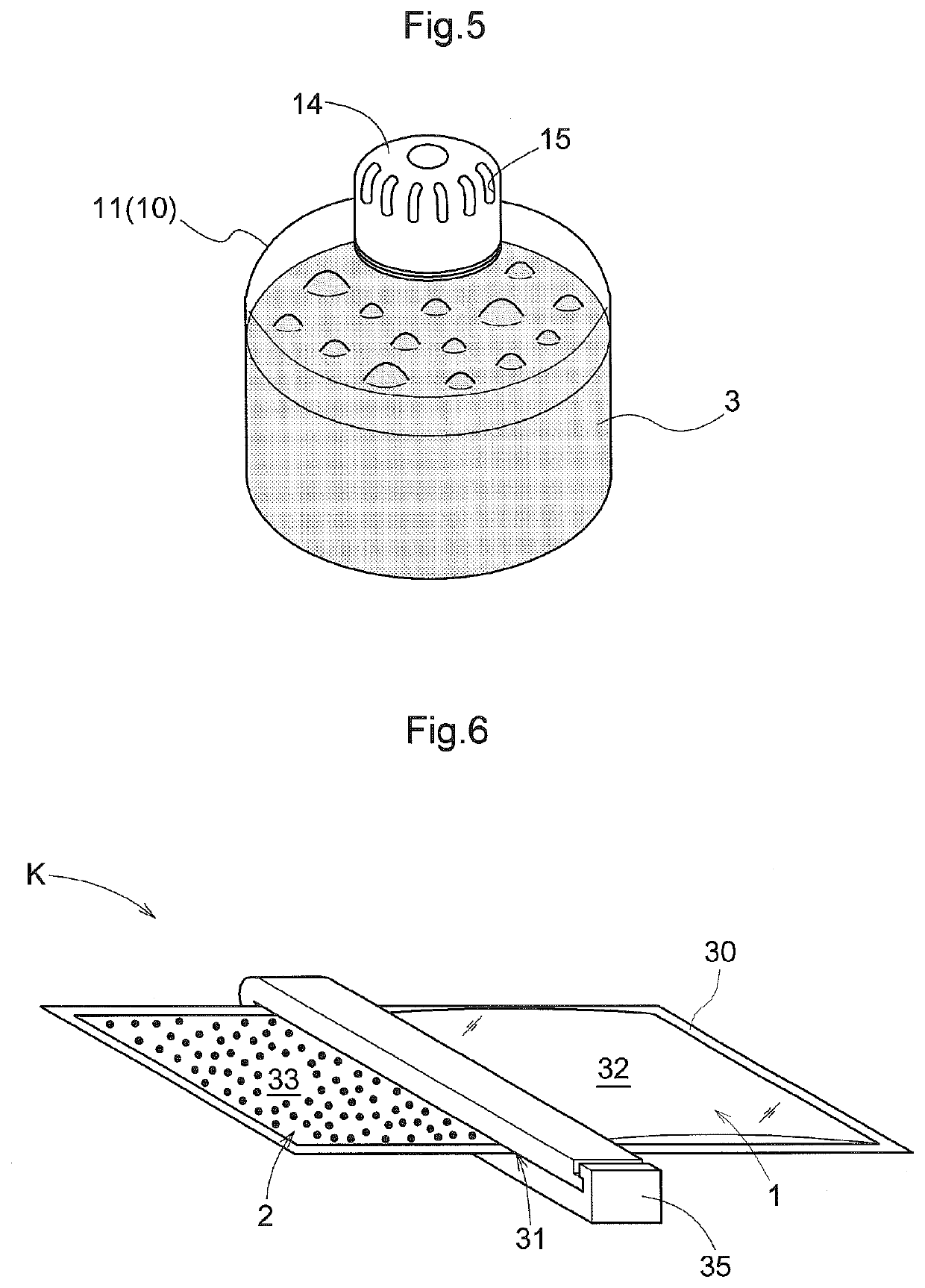
[0094]Hereinafter, the chlorine dioxide gas generating kit K of this embodiment will be described mainly focusing on differences from the first embodiment. Note that constituent elements not specifically described are as in the first embodiment, and thus they are denoted by the same reference numerals, and a description thereof has ...

third embodiment

[0099]Hereinafter, a chlorine dioxide gas generating method, a liquid composition, a gel composition, and a chlorine dioxide gas generating kit according to a third embodiment will be described. In this embodiment, the aqueous chlorite solution, the fast-acting activator, the metal iodide, slow-acting activation inhibitor, and the absorbent resin are allocated to the first agent 1 and the second agent 2 of the chlorine dioxide gas generating kit K in a manner different from that of the first and second embodiments. Furthermore, the specific configuration of the container of the chlorine dioxide gas generating kit K is different from that of the first and second embodiments. Hereinafter, the chlorine dioxide gas generating kit K of this embodiment will be described mainly focusing on differences from the first embodiment. Note that constituent elements not specifically described are as in the first embodiment, and thus they are denoted by the same reference numerals, and a descriptio...


PUM

PropertyMeasurementUnit
pHaaaaaaaaaa
pHaaaaaaaaaa
pHaaaaaaaaaa

Abstract

Chlorine dioxide gas is immediately generated at a stable concentration from a liquid composition. The composition is obtained by mixing an aqueous chlorite solution, an activator that immediately adjusts the pH of the aqueous chlorite solution, an activation inhibitor that slowly mitigates an action of the activator, and a metal iodide such that the metal iodide is contained in a proportion of 0.4% by mass or less and the activation inhibitor is contained in a proportion of 1% by mass or less with respect to 1 L of 1% by mass aqueous chlorite solution.

Description

TECHNICAL FIELD[0001]The present invention relates to a technique for immediately generating chlorine dioxide gas at a stable concentration.BACKGROUND ART[0002]It is known that chlorine dioxide has strong oxidizability, and kills bacteria or degrades offensive odor components through its oxidizing action.[0003]Accordingly, chlorine dioxide is widely used as an antimicrobial agent, a deodorant, a fungicide, bleach, and the like. In these applications, chlorine dioxide is often used in the form of chlorine dioxide gas.[0004]As an example of a chlorine dioxide gas generating method, a method in which an activator such as an organic acid or an inorganic acid is added to an aqueous chlorite solution is disclosed, for example, in JP 2005-29430A (Patent Document 1). In the method disclosed in Patent Document 1, the amount of chlorine dioxide gas generated is adjusted using a gas generation adjuster such as sepiolite or zeolite. Although not specifically described in Patent Document 1, it i...

Claims


Application Information

Patent Timeline
Patent Type & Authority Applications(United States)
IPC IPC(8): C01B11/02A61L2/20A61L2/26A61L9/04A61L9/12A01N59/00B65D81/32
CPCA61L2/26A61L2202/11A61L2/20A61L9/12C01B11/024A01N59/00A61L9/046A61L2209/21B65D81/3266C01B11/022A61L9/01A61L9/015
Inventor ABE, KOJIABE, TSUKASA
Owner CLO2 LAB INC
Learn More