Heat dissipation unit connection structure

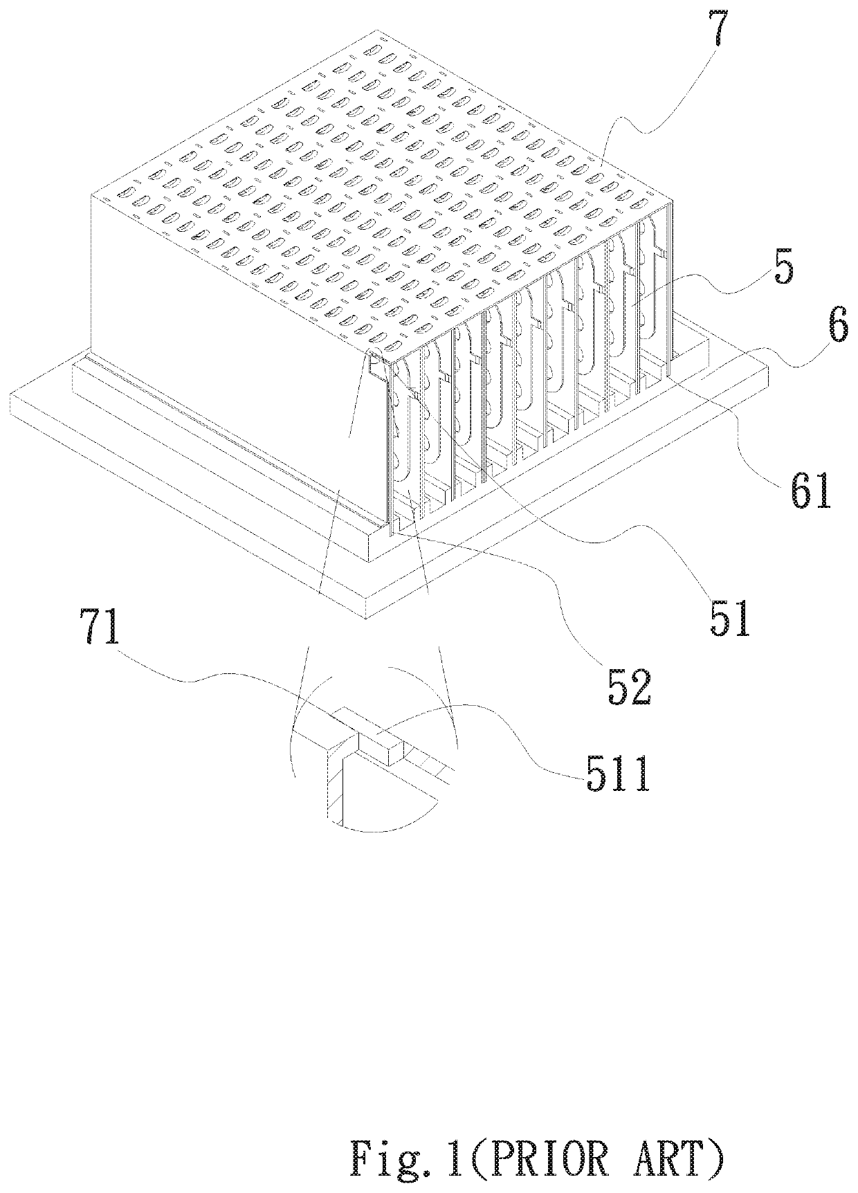
a heat dissipation unit and connection structure technology, applied in the direction of lighting and heating apparatus, stationary conduit assemblies, laminated elements, etc., can solve the problems of increasing difficulty in working, time-consuming, and complicated connection methods for assembling the plate body b>7/b> with the conventional roll-bond plate evaporator b>5/b>, so as to simplify the connection structure and process, shorten the working time, and simplify the effect of structure and process

Inactive Publication Date: 2020-07-23
ASIA VITAL COMPONENTS (CHINA) CO LTD
View PDF12 Cites 0 Cited by
  • Summary
  • Abstract
  • Description
  • Claims
  • Application Information

AI Technical Summary

Benefits of technology

The present invention provides a heat dissipation unit connection structure that is easy to secure and achieves a dustproof effect. The connection structure is simplified and shortens the working time, while reducing manufacturing costs.

Problems solved by technology

The connection method for assembling the plate body 7 with the conventional roll-bond plate evaporators 5 is relatively complicated.
Such process is time-costing and the difficulty in working is increased.
Moreover, once assembled, it is impossible or very hard to rework on the plate body 7.
Furthermore, the securing structure of the conventional roll-bond plate evaporators 5 is too complicated so that the manufacturing cost is relatively high.

Method used


Image

  • Heat dissipation unit connection structure
  • Heat dissipation unit connection structure
  • Heat dissipation unit connection structure

Examples


Embodiment Construction

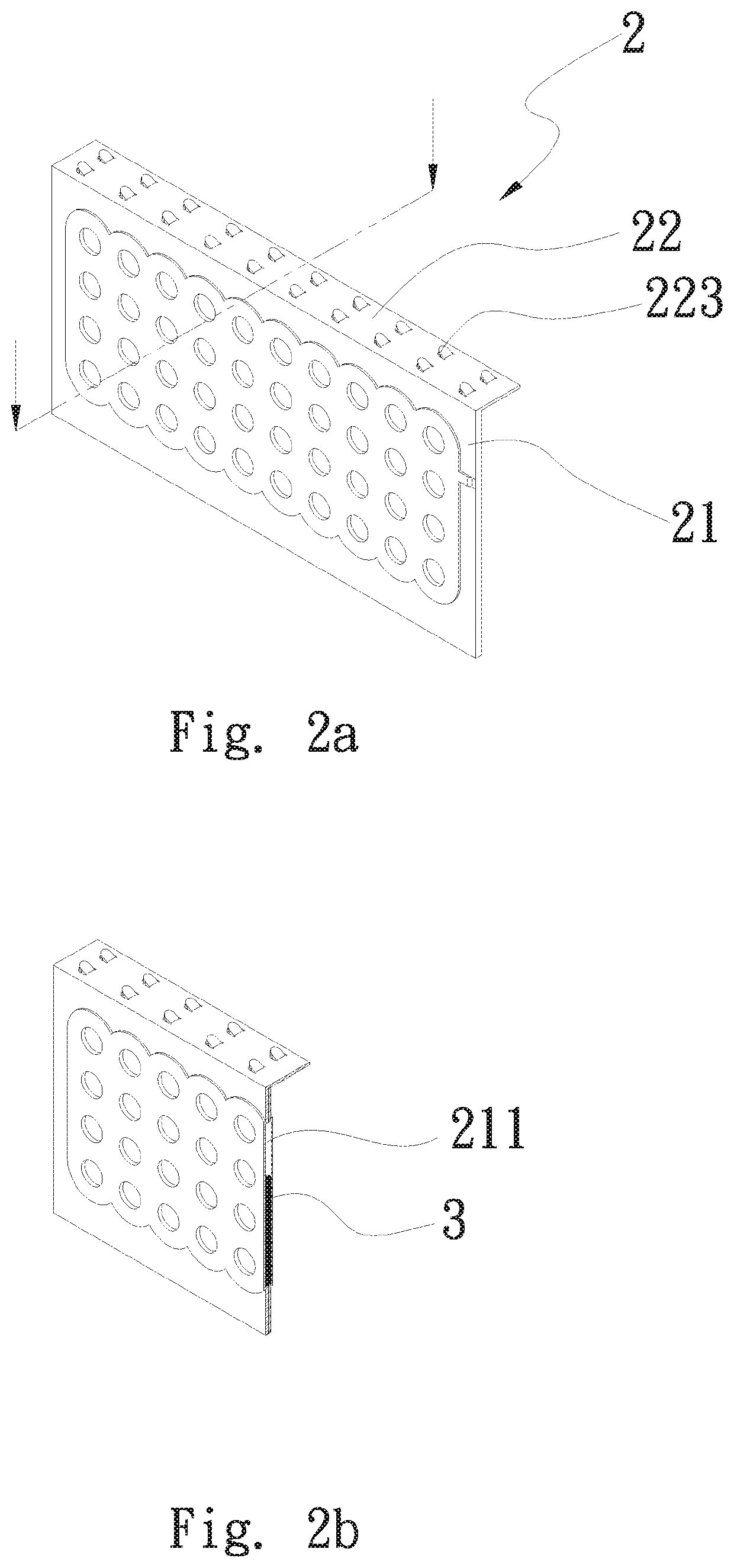
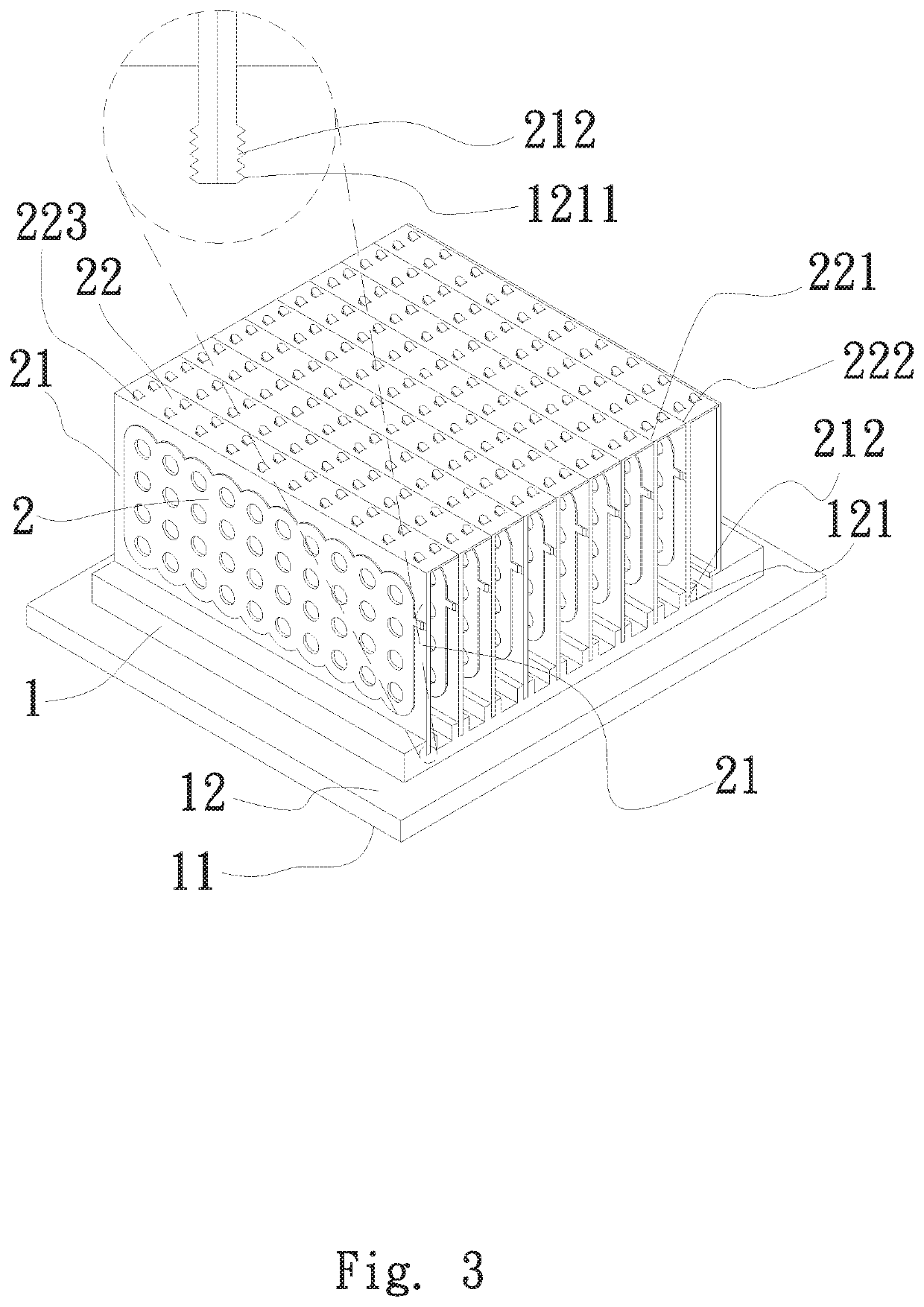
[0023]Please refer to FIGS. 2a, 2b and 3. FIG. 2a is a perspective view of the heat dissipation unit of a first embodiment of the heat dissipation unit connection structure of the present invention. FIG. 2b is a perspective sectional view of the heat dissipation unit of the first embodiment of the heat dissipation unit connection structure of the present invention. FIG. 3 is a perspective assembled view of the first embodiment of the heat dissipation unit connection structure of the present invention. According to the first embodiment, the heat dissipation unit connection structure of the present invention includes a substrate 1 and multiple heat dissipation units 2.

[0024]The substrate 1 has a first face 11 and a second face 12. The first and second faces 11, 12 are respectively positioned on an upper side and a lower side of the substrate 1. The first face 11 is in contact with at least one heat source (not shown) to conduct the heat of the heat source. The second face 12 is formed...


PUM


Abstract

A heat dissipation unit connection structure includes a substrate and multiple heat dissipation units. The substrate has a first face and a second face. Each heat dissipation unit has a first section and a second section. One end of the first section is connected with the second face of the substrate. The first section has an internal space. The second section extends from the other end of the first section. The second sections of each two adjacent heat dissipation units abut against and connect with each other. The heat dissipation unit connection structure improves the shortcoming of the conventional heat dissipation unit connection structure that the structure is too complicated and it is impossible to rework on the heat dissipation unit connection structure.

Description

BACKGROUND OF THE INVENTION1. Field of the Invention[0001]The present invention relates generally to a heat dissipation unit connection structure, and more particularly to a heat dissipation unit connection structure, which can quickly connect the heat dissipation units and save the connection cost.2. Description of the Related Art[0002]Please refer to FIG. 1. In the heat dissipation field, the conventional roll-bond plate evaporator 5 has been widely applied to the radiating fin or the product employing two-phase heat exchange to dissipate the heat. The roll-bond plate evaporator 5 has two faces. One of the two faces of some roll-bond plate evaporator 5 is formed with blown and raised pipelines. A cooling medium, which can be a gas or a liquid, is filled in the pipelines to enhance the heat dissipation performance.[0003]The conventional inserted roll-bond plate evaporators 5 can be classified into two types of structures. One is single-face roll-bond plate evaporator and the other ...

Claims


Application Information

Patent Timeline
Patent Type & Authority Applications(United States)
IPC IPC(8): F28D1/02F28D1/03
CPCF28D1/03F28D1/0233F28D15/0233F28D15/0275F28D2021/0029F28F3/12
Inventor LIN, KUO-SHENG
Owner ASIA VITAL COMPONENTS (CHINA) CO LTD
Why Eureka
Try Eureka