Battery pack

a battery pack and battery technology, applied in the field of batteries, can solve the problems of increased material cost, increased defective ratio of battery packs, high defect ratio of outer appearance, etc., and achieve the effect of reducing defective ratio of batteries, reducing material costs, and increasing coupling strength

Inactive Publication Date: 2009-03-26
SAMSUNG SDI CO LTD
View PDF15 Cites 30 Cited by
  • Summary
  • Abstract
  • Description
  • Claims
  • Application Information

AI Technical Summary

Benefits of technology

[0014]It is another object of the present invention to provide a battery pack that can increase coupling strength between a protection circuit module and an outer case, and realize a compact battery pack by physically coupling the protection circuit module coupled to a bare cell to the integral outer case by an adherent member.
[0015]It is again another object of the present inve

Problems solved by technology

When outer appearance of the battery pack is formed by a hot-melting method using the hot-melt resin, a defective ratio of outer appearance becomes high because of material defective properties, for example air bubble, produced in the hot-melt resin.
Accordingly, there is a problem that a defective ratio of the battery pack is increased.
There is another problem that material costs are increased because the related art battery pack needs a high quantity of the hot-melt resin injected between the bare cell and the protection circuit module so as to form the resin mol

Method used


Image

  • Battery pack
  • Battery pack
  • Battery pack

Examples


case 300

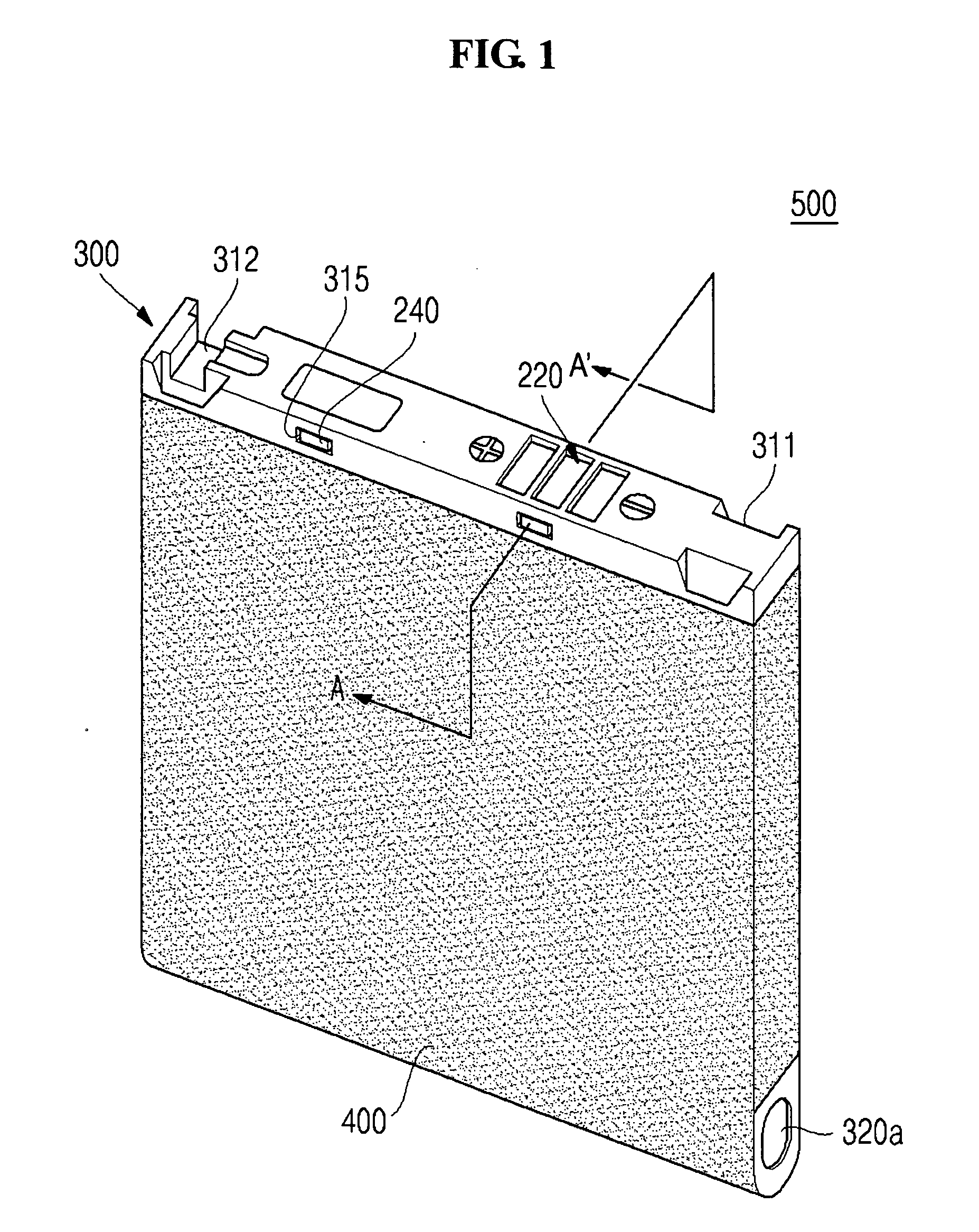
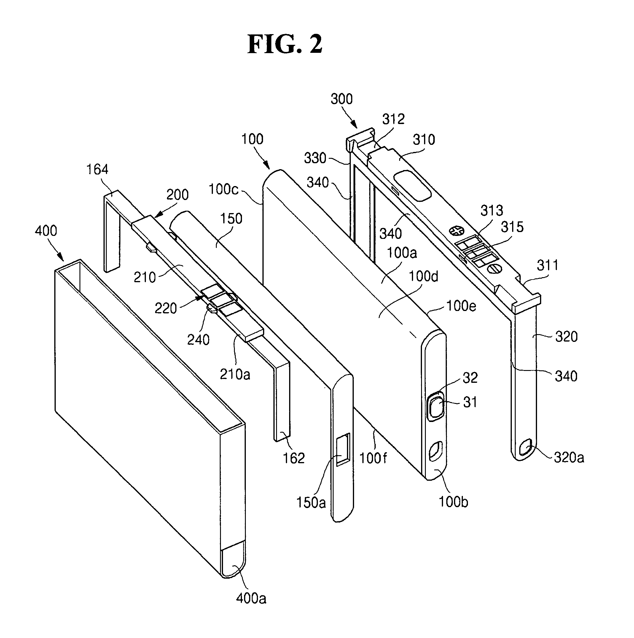
[0066]Outer case 300 is formed to be an integral injection case by an injection molding method so as to cover upper surface 100a and the pair of short side surfaces 100b and 100c of bare cell 100, and then outer case 300 is assembled in circuit module 200 connected to bare cell 100. In this case, outer case 300 is physically coupled to circuit module 200 connected to bare cell 100 by protrusion parts 240 formed on circuit module 200 and receiving grooves 315 formed on outer case 300.

[0067]Outer case 300 is formed integrally with a front surface part 310, a pair of side surface parts 320 and 330, a rim 340 and receiving grooves 315.

[0068]More particularly, front surface part 310 of outer case 300 is formed to be in plate shape having size corresponding to upper surface 100a of bare cell 100 provided with circuit module 200. When front surface part 310 is coupled to circuit module 200 connected to bare cell 100, front surface part 310 covers upper surface 100a of bare cell 100. Front ...

case 800

[0091]Outer case 800 is formed to be an integral injection case by an injection molding method so as to cover an upper surface 600a and a pair of short side surfaces 600b and 600c of bare cell 600, and then outer case 800 is assembled in circuit module 700 connected to bare cell 600.

[0092]Outer case 800 includes a front surface part 810, a pair of side surface parts 820 and 830 and an extended surface part 840. Further, outer case 800 includes a tapered part 814 and a receiving space 815 formed in the inner side thereof. Front surface part 810, the pair of side surface parts 820 and 830, and rim 840 of outer case 800 are the same as front surface part 310, the pair of side surface parts 320 and 330, and rim 340 of outer case 300 respectively as shown in FIG. 4, and thus duplicated explanation will be omitted.

[0093]Tapered part 814 and receiving space 815 formed in the inner side of outer case 800 function as the adherent member to physically couple outer case 800 to circuit module 7...


PUM


Abstract

A battery pack increases coupled strength of a protection circuit module and an outer case, and realize a compact battery pack by physically coupling the protection circuit module coupled to a bare cell and the integral outer case by an adherent member. The battery pack includes a bare cell; a circuit module arranged on an upper surface of the bare cell and electrically coupled to the bare cell; an outer case integrally formed so as to cover a pair of short side surfaces and the upper surface of the bare cell including the circuit module, and coupled to the circuit module; and a label attached to the pair of the short side surfaces, a pair of long side surfaces and a lower surface of the bare cell. At least one protrusion part may be integrally formed an outer side surface of said circuit module. At least one tapered part may be integrally formed with said outer case.

Description

CLAIM OF PRIORITY[0001]This application makes reference to, incorporates the same herein, and claims all benefits accruing under 35 U.S.C. §119 from an application for BATTERY PACK earlier filed in the Korean Intellectual Property Office on 21 Sep. 2007 and there duly assigned Serial No. 2007-0097035.BACKGROUND OF THE INVENTION[0002]1. Field of the Invention[0003]The present invention relates to a battery pack, and more particularly, to a battery pack that can increase production yield by reducing a defective ratio of products and be compacted.[0004]2. Description of the Related Art[0005]Generally, with the development of light weighted and high functionality portable wireless devices such as video cameras, cellular phones, portable computers, and other relate devices, secondary battery used as the main power supply of these portable electronic devices has been actively developed and produced. For example, the secondary battery includes a nickel-cadmium battery, a nickel-hydrogen ba...

Claims


Application Information

Patent Timeline
IPC IPC(8): H01M2/02H01M2/00
CPCH01M2/1061H01M10/425H01M2/22Y02E60/10H01M50/528Y02P70/50H01M50/202H01M50/247H01M50/284H01M50/296H01M10/4257H01M50/256H01M2200/00
Inventor KOH, SEOKSEO, KYUNGWONBYUN, JEONGDEOKPARK, KYUNGHOKWAK, EUNOK
Owner SAMSUNG SDI CO LTD
Why Eureka
Try Eureka