Organic EL device, method of manufacturing the same and electronic apparatus

a technology of electroluminescent devices and electronic devices, applied in the manufacture of electrode systems, electric discharge tubes/lamps, discharge tubes luminescent screens, etc., can solve the problems of increased manufacturing costs, interference and achieve the effect of improving the chromaticity of emitted light components, increasing manufacturing costs, and complicated manufacturing processes

Active Publication Date: 2005-05-12
SEIKO EPSON CORP
View PDF10 Cites 31 Cited by
  • Summary
  • Abstract
  • Description
  • Claims
  • Application Information

AI Technical Summary

Benefits of technology

[0006] A technique disclosed in Patent Document 1 aims to improve the chromaticity of emitted light components by allowing the specified wavelength among the emitted light components to be resonated. However, in the technique disclosed in Patent Document 1, when manufacturing a

Problems solved by technology

However, in the technique disclosed in Patent Document 1, when manufacturing a color display device using an EL element, since the optimized minute optical resonators must be provided in the respective pixels of red (R), green (G) and blue (B), there

Method used


Image

  • Organic EL device, method of manufacturing the same and electronic apparatus
  • Organic EL device, method of manufacturing the same and electronic apparatus
  • Organic EL device, method of manufacturing the same and electronic apparatus

Examples


experimental example 1

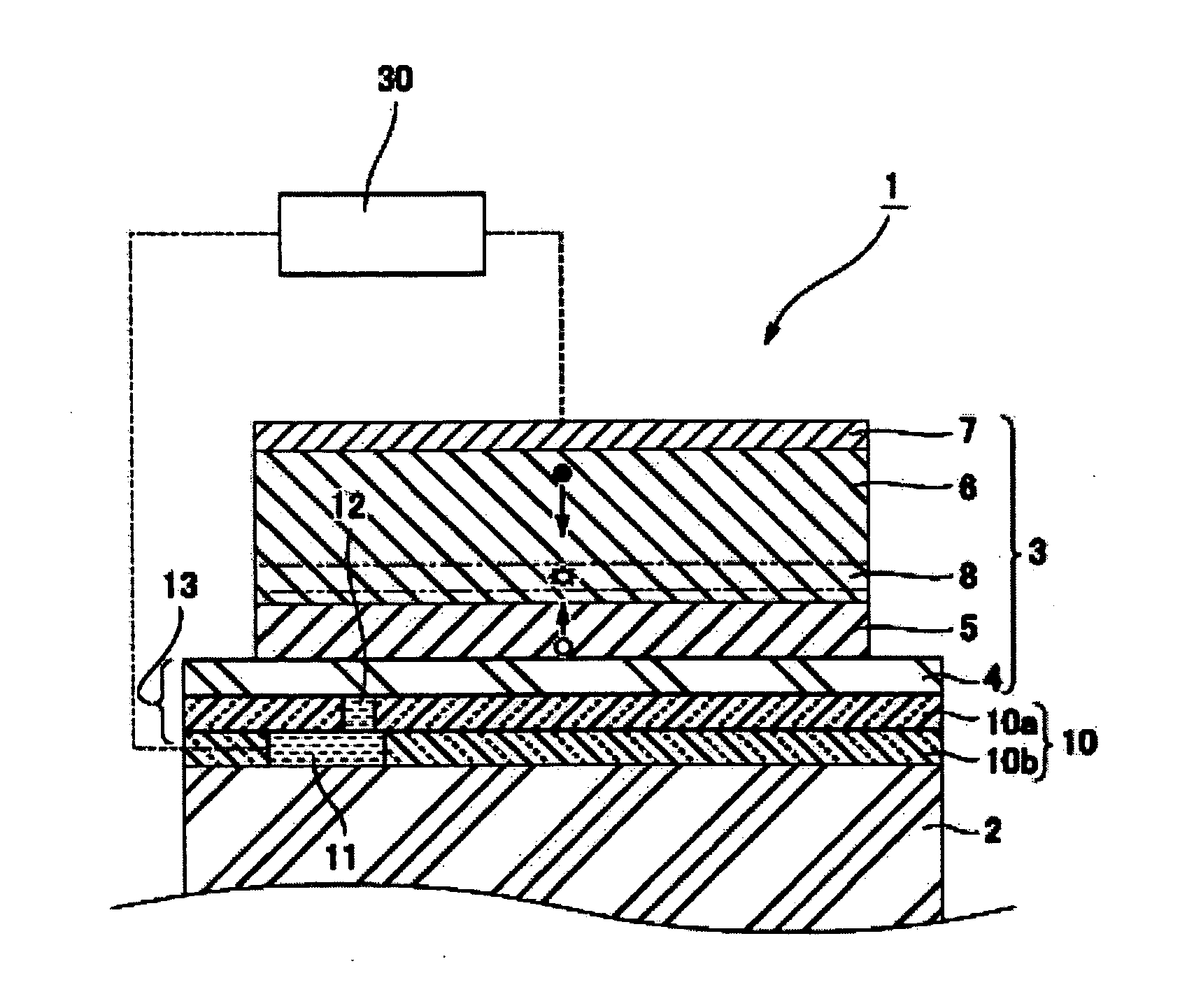
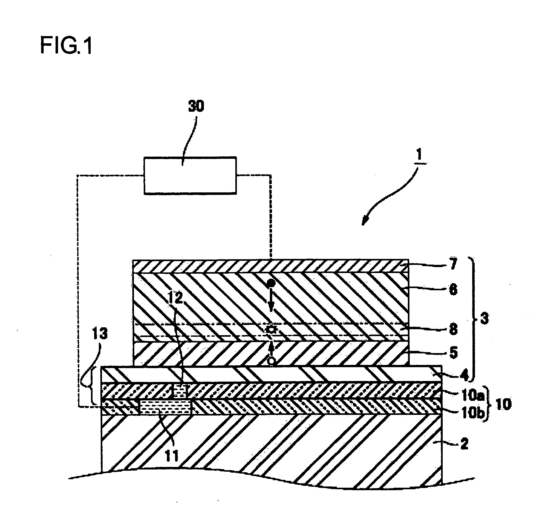
[0064] First, the TFT element 11 was provided on the transparent substrate 2, and thereon the second insulating layer 10b made of silicon oxide was formed. Next, the anode 4 made of ITO was laminated on the second insulating layer 10b, the hole injecting layer 5 made of polyethylenedioxythiophene (PEDOT) was laminated on the anode 4 by using the liquid droplet discharging method, and the light-emitting layer 6 made of green light-emitting material was laminated on the hole injecting layer 5 by using the liquid droplet discharging method. Subsequently, the cathode 7 was formed on the light-emitting layer 6 while sealing with a sealing material. In the present example, since the first insulating layer 10a is not formed, the light-transmitting layer 13 comprises only the anode 4. However, even though the light-transmitting layer 13 comprises the anode 4 and the first insulating layer 10a, the same results can be obtained if the optical length of the light-transmitting layer 13 is the s...

experimental example 2

[0069] First, the TFT element 11 was provided on the transparent substrate 2, and thereon the second insulating layer 10b made of silicon oxide was formed. Next, the anode 4 made of ITO was laminated on the second insulating layer 10b, the hole injecting layer 5 made of polyethylenedioxythiophene (PEDOT) was laminated on the anode 4 by using the liquid droplet discharging method, and the light-emitting layer 6 made of blue light-emitting material was laminated on the hole injecting layer 5 by using the liquid droplet discharging method. Subsequently, the cathode 7 was formed on the light-emitting layer 6 while sealing with a sealing material. In the present example, since the first insulating layer 10a is not formed, the light-transmitting layer 13 comprises only the anode 4. However, even though the light-transmitting layer 13 comprises the anode 4 and the first insulating layer 10a, the same results can be obtained if the optical length of the light-transmitting layer 13 is the sa...


PUM

PropertyMeasurementUnit
Thicknessaaaaaaaaaa
Thicknessaaaaaaaaaa
Thicknessaaaaaaaaaa

Abstract

To provide an organic EL device which is capable of forming a minute optical resonator in a light-emitting element and improving the chromaticity of color light components to be emitted, without complicating a manufacturing process, a method of manufacturing the organic EL device, and an electronic apparatus. In an organic EL device 1, each element comprises an anode 4 and a first insulating layer 10a, a light-transmitting layer 13 having a refractive index larger than that of a transparent substrate 2, a cathode 7 having light reflection which oppose a transparent electrode 4, and an organic functional layer including a light-emitting layer 6 and a hole injecting layer 5. In green color light-emitting elements, a first optical length, which is the sum of the product of film thickness and refractive index of the hole injecting layer and the product of film thickness and refractive index of the light-emitting layer, is 250 nm or less, and in blue color light-emitting elements, a second optical length, which is the sum of the product of film thickness and refractive index of the hole injecting layer and the product of film thickness and refractive index of the light-emitting layer, is 230 nm or less. A third optical length, which is the product of film thickness and refractive index of the light-transmitting layer 13, is 300 nm or less.

Description

BACKGROUND OF THE INVENTION [0001] 1. Field of Invention [0002] The present invention relates to an organic electro-luminescent (EL) device having a plurality of light-emitting elements for emitting predetermined color light components on a transparent substrate, a method of manufacturing the organic EL device, and an electronic apparatus. [0003] 2. Description of Related Art [0004] As a next generation display device, an organic EL device having a plurality of electroluminescent (EL) elements on a transparent substrate has been expected. The organic EL device has light-emitting elements in which an organic functional layer including a light-emitting layer is interposed between an anode and a cathode. In such an organic EL device, holes injected from the anode and electrons injected from the cathode are recombined in the light-emitting layer to emit light when deactivated from the excited state. Further, an EL device which increases light having a specified wavelength by using a min...

Claims


Application Information

Patent Timeline
IPC IPC(8): H01L27/32H01L51/00H01L51/50H05B33/24H01L51/52H05B33/00H05B33/10H05B33/14H05B33/22H05B33/28
CPCH01L27/3211H01L27/3244H01L51/0037H01L2251/558H01L51/0081H01L51/5265H01L51/0078H10K59/35H10K59/12H10K85/1135H10K85/311H10K85/324H10K50/852H10K2102/351
Inventor KOBAYASHI, HIDEKAZU
Owner SEIKO EPSON CORP
Why Eureka
Try Eureka