

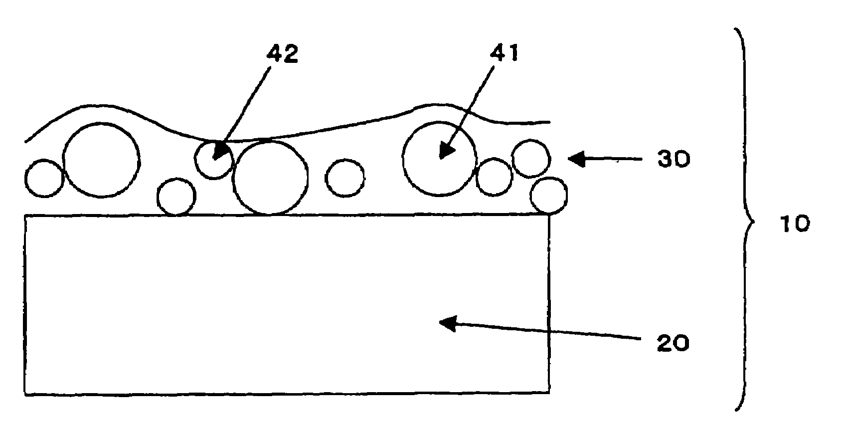
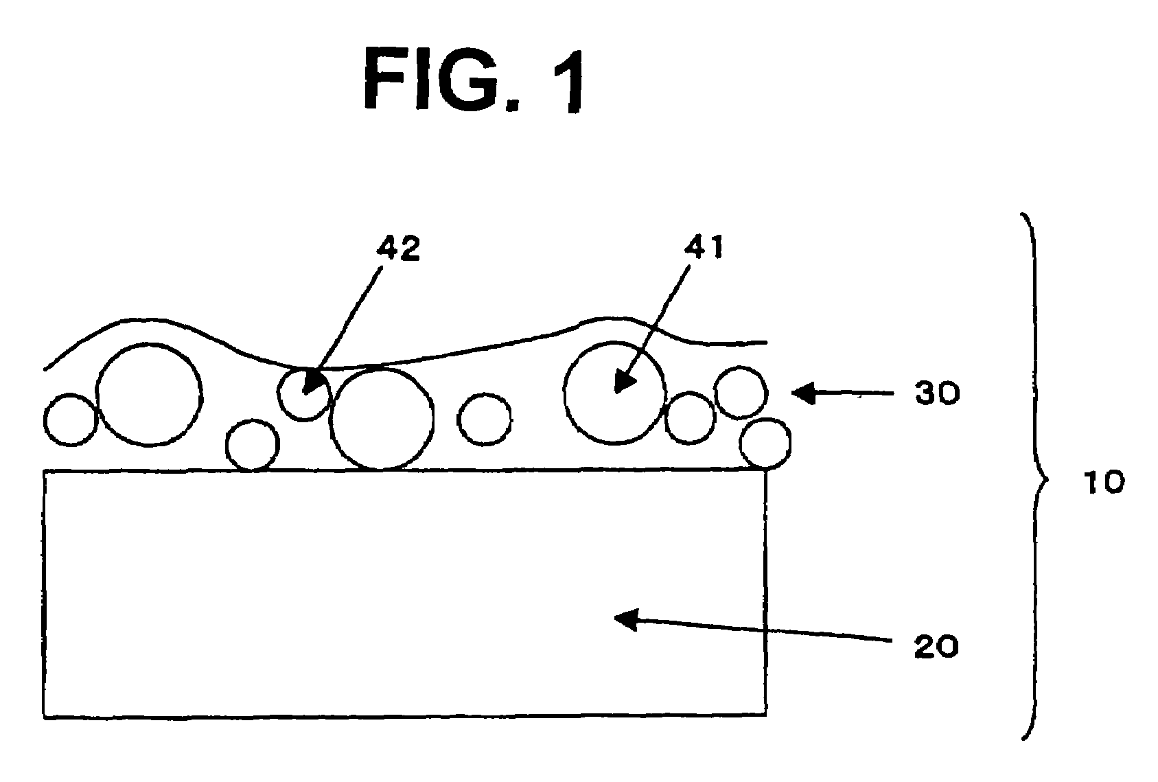
Liquid crystal display of transmission type
a technology of liquid crystal display and transmission type, which is applied in the direction of identification means, instruments, coatings, etc., can solve problems such as affecting image quality, and achieve the effect of widening the viewing angl
- Summary
- Abstract
- Description
- Claims
- Application Information
AI Technical Summary
Benefits of technology
Problems solved by technology
Method used
Image

Examples
example 1
[0224]A pair of polarizing films were removed from a commercially available liquid crystal display of TN mode (6E-A3, Sharp Corporation). In place of the removed polarizing films, the polarizing film (SHB-01) was laminated on the observer side surface with adhesive so that the film KH-01 might be on the liquid crystal cell side. On the backlight side, the polarizing film (SHB-H1) was laminated with adhesive so that the film KH-01 might be on the liquid crystal cell side. The polarizing plate on the observer side and that on the backlight side were placed so that the transparent axes of the observer side plate and the backlight side plate might be arranged in 0 mode. Thus, the liquid crystal display was prepared.
[0225]The viewing angle of the prepared liquid crystal display was measured by means of a measuring apparatus (EZ-Contrast 160D, ELDIM) when each of the eight tones of black (L1) to white (L8) was displayed. Further, the chromaticity difference at middle tone (L3) was also me...
example 2
[0226]A pair of polarizing films were removed from a commercially available liquid crystal display of TN mode (6E-A3, Sharp Corporation). In place of the removed polarizing films, the polarizing film (SHB-02) was laminated on the observer side surface with adhesive so that the film KH-01 might be on the liquid crystal cell side. On the backlight side, the polarizing film (SHB-H1) was laminated with adhesive so that the film KH-01 might be on the liquid crystal cell side. The polarizing plate on the observer side and that on the backlight side were placed so that the transparent axes of the observer side plate and the backlight side plate might be arranged in 0 mode. Thus, the liquid crystal display was prepared.
[0227]The viewing angle of the prepared liquid crystal display was measured by means of a measuring apparatus (EZ-Contrast 160D, ELDIM) when each of the eight tones of black (L1) to white (L8) was displayed. Further, the chromaticity difference at middle tone (L3) was also me...
example 3
[0228]A pair of polarizing films were removed from a commercially available liquid crystal display of TN mode (6E-A3, Sharp Corporation). In place of the removed polarizing films, the polarizing film (SHB-03) was laminated on the observer side surface with adhesive so that the film KH-01 might be on the liquid crystal cell side. On the backlight side, the polarizing film (SHB-H1) was laminated with adhesive so that the film KH-01 might be on the liquid crystal cell side. The polarizing plate on the observer side and that on the backlight side were placed so that the transparent axes of the observer side plate and the backlight side plate might be arranged in 0 mode. Thus, the liquid crystal display was prepared.
[0229]The viewing angle of the prepared liquid crystal display was measured by means of a measuring apparatus (EZ-Contrast 160D, ELDIM) when each of the eight tones of black (L1) to white (L8) was displayed. Further, the chromaticity difference at middle tone (L3) was also me...
PUM
| Property | Measurement | Unit |
|---|---|---|
| particle size | aaaaa | aaaaa |
| particle size | aaaaa | aaaaa |
| haze | aaaaa | aaaaa |
Abstract
Description
Claims
Application Information