Dropping nozzle and molding apparatus

a technology of molding apparatus and drop nozzle, which is applied in the direction of glass pressing apparatus, glass making apparatus, manufacturing tools, etc., can solve the problems of low stability of weight, difficult processing of the cylindrical part, and complicated processing of the reference surface on the side of the distal end of the nozzle. , to achieve the effect of reducing the variation in the weight of the glass drop and avoiding the wetting of molten glass

Inactive Publication Date: 2020-08-06
KONICA MINOLTA INC
View PDF2 Cites 1 Cited by
  • Summary
  • Abstract
  • Description
  • Claims
  • Application Information

AI Technical Summary

Benefits of technology

[0007]The present invention has been made in view of the related art described above. It is an object of the present invention to provide a dropping nozzle that avoids wetting-up of molten glass and reduces a variation in weight of a glass drop.

Problems solved by technology

The dropping nozzle disclosed in JP 2010-235425 A has a problem in which processing is difficult due to a complicated shape of the distal end of the nozzle, and a problem in which glass comes into contact with a complicated structure of the distal end of the nozzle and drops, and this results in a low stability of weight.
In addition, the dropping nozzle disclosed in JP 2013-43792 A has a problem in which the processing of the reference surface on a side of the distal end of the nozzle and the cylindrical part is complicated, and a problem in which the quality of a molded body deteriorates due to a difference in temperature between glass in a wetting-up part and glass inside the nozzle.

Method used


Image

  • Dropping nozzle and molding apparatus
  • Dropping nozzle and molding apparatus
  • Dropping nozzle and molding apparatus

Examples


first embodiment

[0020]A dropping nozzle according to a first embodiment of the present invention and a molding apparatus including the dropping nozzle are described with reference to FIG. 1 and the like.

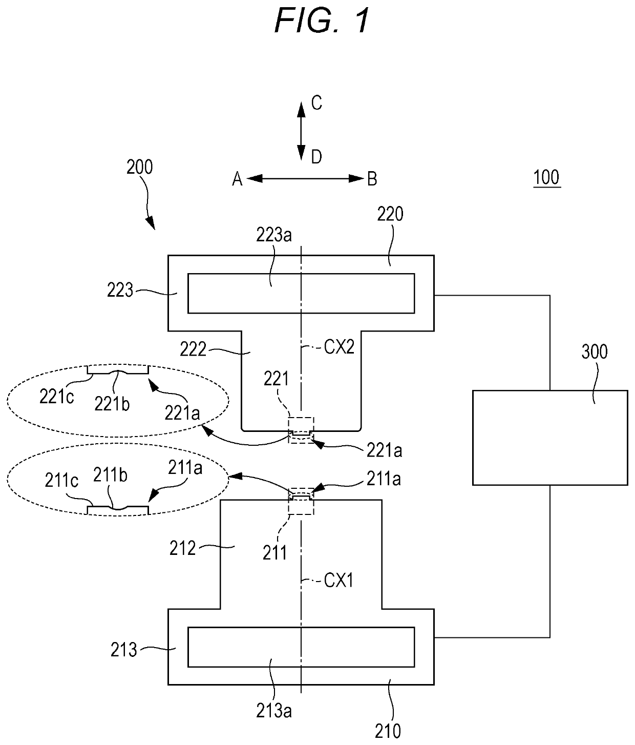
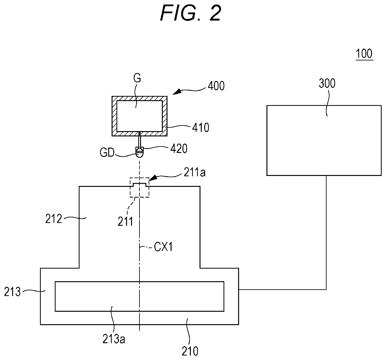
[0021]As illustrated in FIGS. 1 and 2, a molding apparatus 100 is an apparatus for pressure molding that melts glass serving as a raw material of a molded body and directly presses the glass. The molding apparatus 100 includes a mold 200, a control driving device 300, and a glass drop forming device 400.

[0022]As illustrated in FIG. 1, the mold 200 includes a first mold 210 and a second mold 220. In molding, the first mold 210 moves so as to face the second mold 220, and a mold closing operation is performed in such a way that both molds 210 and 220 abut onto each other.

[0023]The first mold 210 includes a first mold body 211, a first support part 212, and a first heater 213. In the first mold 210, the first mold body 211 has a cylindrical shape, and includes a first transfer surface 211a. The first t...

examples

[0048]Examples of the dropping nozzle according to the embodiment are described below. As a glass material, phosphoric acid-based glass (glass transition temperature Tg: 480° C.; aid specific gravity: 3.2) was used. This glass material was melted, and a glass drop was dropped by using a dropping nozzle that was heated to 1000° C. The sizes and shapes of dropping nozzles used in examples and a comparative example are indicated in Table 1 described below. In Table 1, the diameter of a nozzle is the diameter of an opening at an endmost part of a dropping nozzle. Nozzle 1 and Nozzle 2 are examples, and have a configuration in which an opening part includes two inclined parts (a configuration having two-stage inclination angles). Nozzle 3 is a comparative example, and has a configuration in which an opening part includes one inclined part (a configuration having a single inclination angle).

TABLE 1InclinationInclinationThick-Diameterangleanglenessϕ (mm)(°) of first(°) of second(mm) ofDrop...

second embodiment

[0053]A dropping nozzle according to a second embodiment of the present invention is described below. The dropping nozzle according to the second embodiment is obtained by transforming the dropping nozzle according to the first embodiment, and matters that are not described otherwise are similar to matters in the first embodiment.

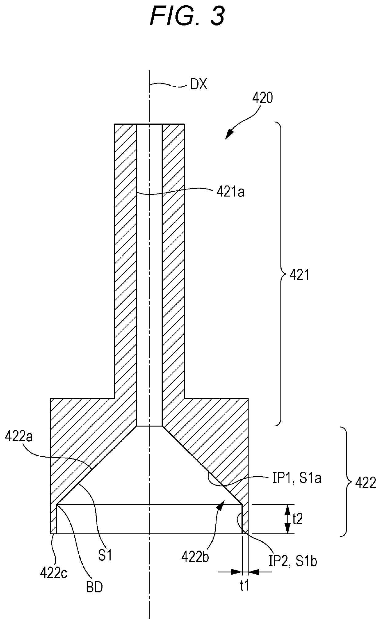
[0054]As illustrated in FIG. 7, at least some of inner surfaces S1 of inclined parts 422b include a curved surface S1c (a surface having a continuously variable angle, such as a circular arc). In the present embodiment, the inner surfaces S1 of the inclined parts 422b include a first inner surface S1a that corresponds to a first inclined part IP and a second inner surface S1b that corresponds to a second inclined part IP2, and the first inner surface S1a includes the curved surface S1c. Here, an inclination angle of the first inclined part IP1 has been set to an angle obtained by averaging or approximating the curved surface S1c having, for example, a circu...


PUM

PropertyMeasurementUnit
thicknessaaaaaaaaaa
thicknessaaaaaaaaaa
lengthaaaaaaaaaa

Abstract

A dropping nozzle includes: a flow passage part that includes a flow passage that molten glass passes through; and an opening part that includes an opening that communicates with the flow passage, the opening part dropping the molten glass as a glass drop, wherein the opening includes a plurality of inclined parts in which adjacent inner inclination angles are different from each other in a section parallel to a center axis of the flow passage part, and from among the plurality of inclined parts, a first inclined part that is closest to the flow passage part has an inner inclination angle that is smaller than an inner inclination angle of a second inclined part that is farthest from the flow passage part.

Description

[0001]The entire disclosure of Japanese patent Application No. 2019-016962, filed on Feb. 1, 2019, is incorporated herein by reference in its entirety.BACKGROUNDTechnological Field[0002]The present invention relates to a dropping nozzle that forms a glass drop to be used to mold a glass molded body, and a molding apparatus that includes the dropping nozzle.Description of the Related Art[0003]A method has been provided for dropping a glass drop by using a dropping nozzle when a molded lens or a gob (a glass gob) is manufactured. An example of a dropping nozzle that forms a glass drop is a dropping nozzle in which ruggedness is formed at part of or the entirety of a distal end of the nozzle and a bent part having an inner angle of 30° or more and 120° or less is included in part of a projection of the ruggedness (see JP 2010-235425 A). In addition, the thickness of the nozzle disclosed in JP 2010-235425 A ranges from 0.3 mm to 1.0 mm. In the nozzle disclosed in JP 2010-235425 A, wetti...

Claims


Application Information

Patent Timeline
Patent Type & Authority Applications(United States)
IPC IPC(8): C03B7/088C03B11/00
CPCC03B7/088C03B11/00C03B11/125C03B2215/61C03B2215/76C03B11/08C03B7/084
Inventor OOMORI, YASUOMACHIDA, CHIAKIKAMIKURA, TAKAYUKI
Owner KONICA MINOLTA INC
Why Eureka
Try Eureka