
Device and method for detecting failure location of underground cable

a technology of underground cable and fault location, which is applied in the direction of fault location by pulse reflection method, fault location by conductor type, instruments, etc., can solve the drawback of small defect detection difficulty, inaccurate detection and prediction of fault location, and the inability of galvanometers to accurately measure current or measurement errors, etc. problems, to achieve the effect of preventing signal analysis distortion, accurate detection and prediction, and detecting fault location

Active Publication Date: 2020-08-06
KOREA ELECTRIC POWER CORP
View PDF0 Cites 8 Cited by
  • Summary
  • Abstract
  • Description
  • Claims
  • Application Information

AI Technical Summary

Benefits of technology

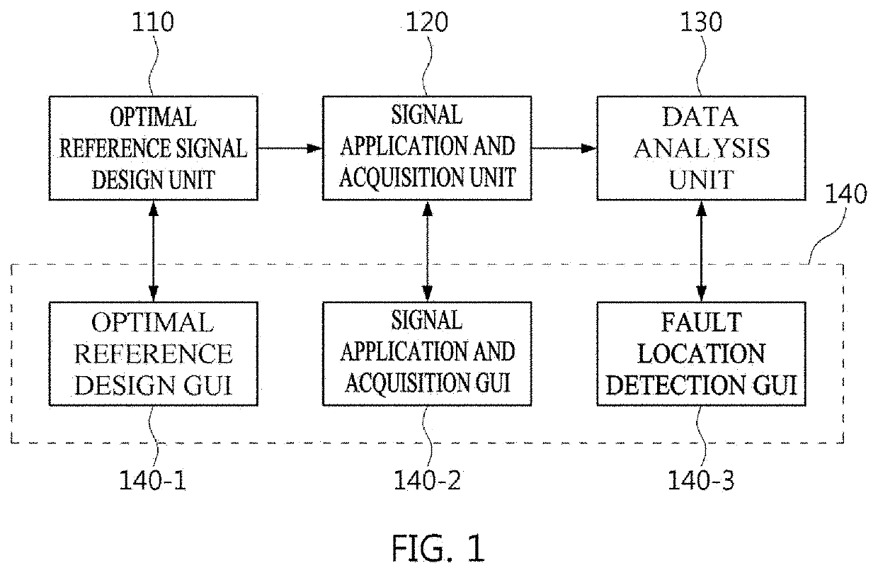
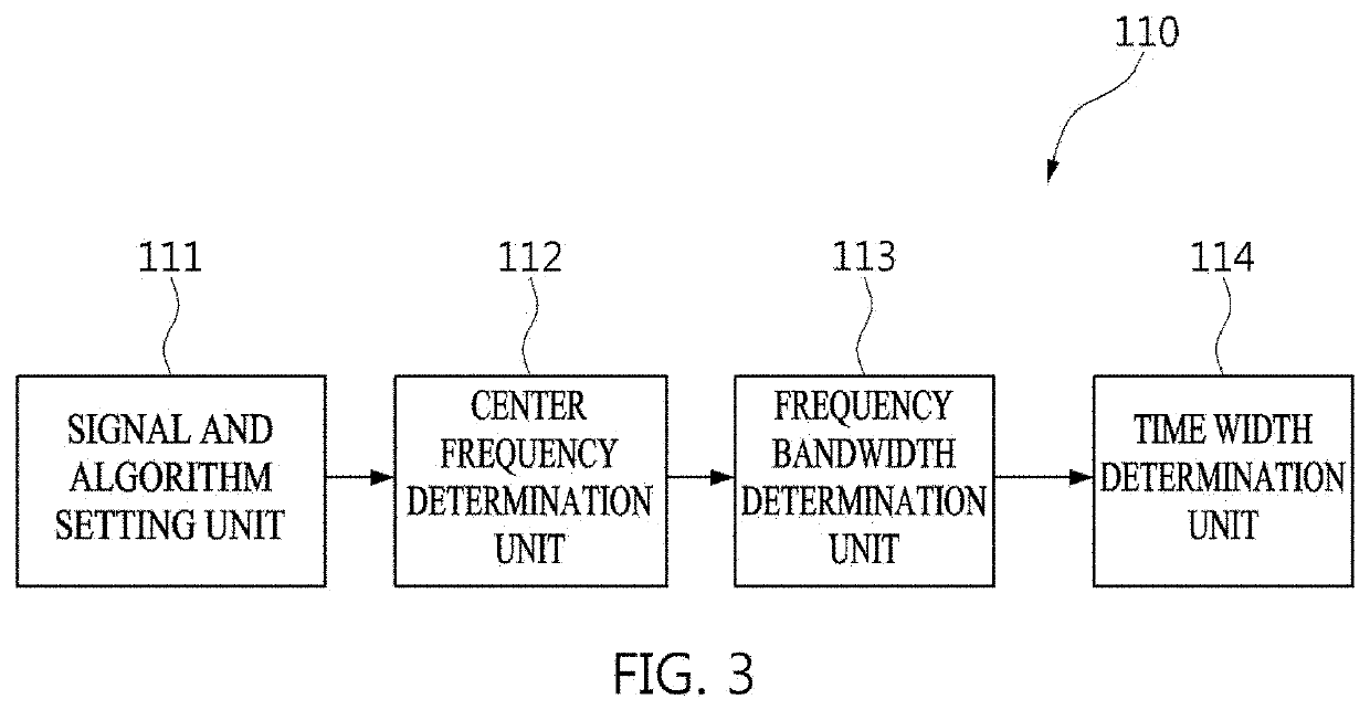
The present invention is designed to accurately detect and predict faults in underground cables by using a time-frequency domain reflectometry method. The invention takes into account the unique characteristics of the cable and its installation to create an optimal reference signal. This helps eliminate distortion in the signal analysis and prevents misrecognition of fault locations due to cross-term. By selecting the center frequency and time width based on the cable's attenuation characteristics and uncertainty principle, the invention minimizes signal distortion and ensures accurate diagnosis of the underground cable's fault location.

Problems solved by technology

Meanwhile, the Murray loop method is advantageous in increasing DC voltage as much as possible for accurate measurement and has a drawback that, when a ground resistance value at the point of the fault is high, the current flowing to the ground is small so that the galvanometer may not accurately measure the current or the measurement error may increase.
The TDR method and ARM use a principle of impedance variation in the event of a fault occurrence but have a disadvantage of being very expensive and are difficult for detecting the fault location in the case of a high resistance fault.
Meanwhile, the TDR method and the FDR method may observe the reflected wave at the impedance mismatch point according to a principle of the reflected wave processing method, but have a drawback of difficulty of detecting small defects due to limitation of the resolution.
In addition, the TDR method and the FDR method have a limitation for the use for local insulation breakdown inspection and defect detection on an actual cable, due to distortion of the reflected waveform.
In addition, according to an uncertainty principle of signal and information theory, the TDR method and the FDR method are not allowed to arbitrarily have very small resolution of the time domain and frequency domain at the same time.
However, the time-frequency domain reflectometry method has introduced flexibility to the reference signal design area where the conventional reflectometry method used to have limitations.

Method used


Image

  • Device and method for detecting failure location of underground cable
  • Device and method for detecting failure location of underground cable
  • Device and method for detecting failure location of underground cable

Examples


Embodiment Construction

[0048]Hereinafter, exemplary embodiments of the present invention will be described in detail with reference to the accompanying drawings. However, in the following description and accompanying drawings, detailed descriptions of well-known functions or configurations that may obfuscate the subject matter of the present invention are omitted. In addition, it should be noted that the same components throughout the drawings are denoted by the same reference numerals as much as possible.

[0049]The terms or words used in the present specification and claims described below should not be interpreted as being limited to ordinary or dictionary meanings and, on the basis of the principle that the inventor may properly define his or her invention in terms that best describe the invention, should be interpreted as meaning and concept consistent with the technical idea of the present invention.

[0050]Therefore, the embodiments described in this specification and configurations shown in the drawin...


PUM


Abstract

An apparatus and a method for detecting a fault location of an underground cable are proposed. The apparatus includes: an optimal reference signal design unit configured to design a reference signal for detecting the fault location of the underground cable considering propagation characteristics of the underground cable according to a time-frequency domain reflectometry method; a signal application and acquisition unit configured, as the designed reference signal is generated and applied to the underground cable, to acquire the reference signal applied to the underground cable and a reflected signal of the applied reference signal; and a data analysis unit configured to analyze whether a fault location of the underground cable exists according to a decision on similarity between the reference signal and the reflected signal after obtaining a time-frequency domain energy distribution for the acquired reference signal and reflected signal.

Description

CROSS-REFERENCE TO RELATED APPLICATIONS[0001]This application claims the benefit under 35 U.S.C. Section 371, of PCT International Application No. PCT / KR2018 / 009811, filed on Aug. 24, 2018, which claimed priority to Korean Patent Application No. KR 10-2017-0138072, filed on Oct. 24, 2017, the disclosures of which are hereby incorporated by the references.TECHNICAL FIELD[0002]The present invention relates to an apparatus and a method for detecting a fault location of an underground cable. More particularly, the present invention relates to an apparatus and a method for detecting a fault location of an underground cable, the apparatus and method being configured to design an optimal reference signal in consideration of propagation characteristics of the underground cable using a time-frequency domain reflectometry method and to analyze a reflected signal obtained by applying the reference signal to the underground cable that is an object to be diagnosed, and the reference signal, ther...

Claims


Application Information

Patent Timeline
Patent Type & Authority Applications(United States)
IPC IPC(8): G01R31/11G01R31/08
CPCG01R31/083G01R31/088G01R31/11
Inventor JUNG, CHAE-KYUNSHIN, YONG-JUNEKWON, GU-YOUNGKIM, TAE-KYUNHWANG, JAE-SANG
Owner KOREA ELECTRIC POWER CORP
Learn More