
Lane departure prevention system of vehicle

a technology of lane departure prevention and vehicle, which is applied in the direction of vehicle components, control devices, driver input parameters, etc., can solve the problems of vehicle oversteering behavior, vehicle may enter a spinning state, and the lateral force of the turning inside wheel may be insufficient, so as to reduce the likelihood

Active Publication Date: 2020-08-13
TOYOTA JIDOSHA KK
View PDF0 Cites 0 Cited by
  • Summary
  • Abstract
  • Description
  • Claims
  • Application Information

AI Technical Summary

Benefits of technology

The patent describes a system that prevents a vehicle from leaving the road or spinning. It does this by applying a braking force to the inner wheel of the vehicle to prevent it from turning too sharply. The system also determines if there is a likelihood of the vehicle entering a spinning state and applies a different braking force to prevent that from happening. This results in a safer driving experience for the vehicle and reduces the likelihood of accidents.

Problems solved by technology

When there is a likelihood that a vehicle will depart from a traveling lane to a turning outside and a braking force is applied to the turning inside wheel in a situation in which the vehicle travels on a road of which a road surface has a low frictional coefficient (hereinafter referred to as a “low-μ road”), a lateral force of the turning inside wheel may be insufficient due to a decrease in the lateral force of the turning inside wheel and traveling of the vehicle may be destabilized.
Particularly, when the lateral force of the turning inside rear wheel is insufficient, there is concern that the vehicle may exhibit over-steering behavior and enter a spinning state.
Accordingly, even with the vehicle having the behavior control device mounted therein, it is not possible to effectively reduce concern that the vehicle will enter a spinning state due to application of a lane departure prevention yaw moment to the vehicle and insufficiency of the lateral force of the turning inside rear wheel in a situation in which there is concern that the vehicle will depart from the traveling lane to the turning outside.

Method used


Image

  • Lane departure prevention system of vehicle
  • Lane departure prevention system of vehicle
  • Lane departure prevention system of vehicle

Examples


first embodiment

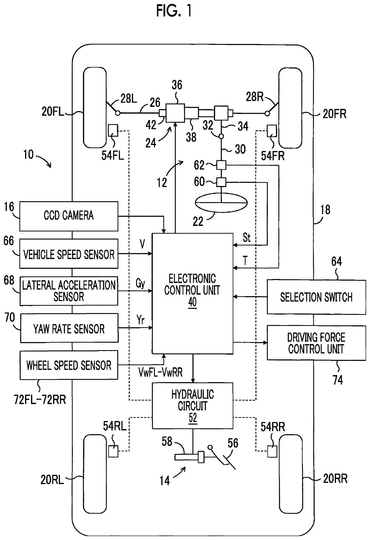
[0062]FIG. 1 is a diagram schematically illustrating a configuration of a lane departure prevention system 10 of a vehicle according to a first embodiment of the disclosure.

[0063]In FIG. 1, the lane departure prevention system 10 is applied to a vehicle 18 including a steering device 12 and a brake device 14 and includes a CCD camera 16 and an electronic control unit 40. The CCD camera 16 is disposed in a front part of a vehicle interior of the vehicle 18, and images the front side of the vehicle 18. As will be described later in detail, the electronic control unit 40 determines whether there is a likelihood that the vehicle 18 will depart from a lane which is not illustrated in FIG. 1 to the turning outside based on the detection result of the CCD camera 16. When it is determined that there is a likelihood that the vehicle 18 will depart from the lane to the turning outside, the electronic control unit 40 controls the brake device 14 such that a lane departure prevention yaw moment...

second embodiment

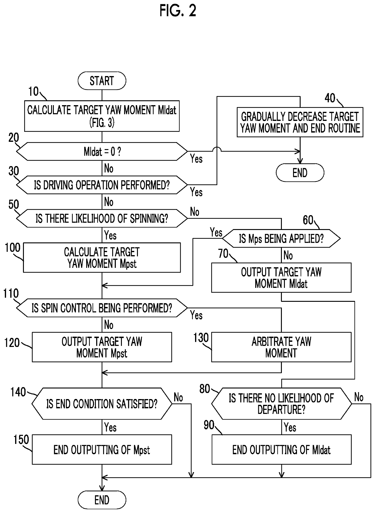
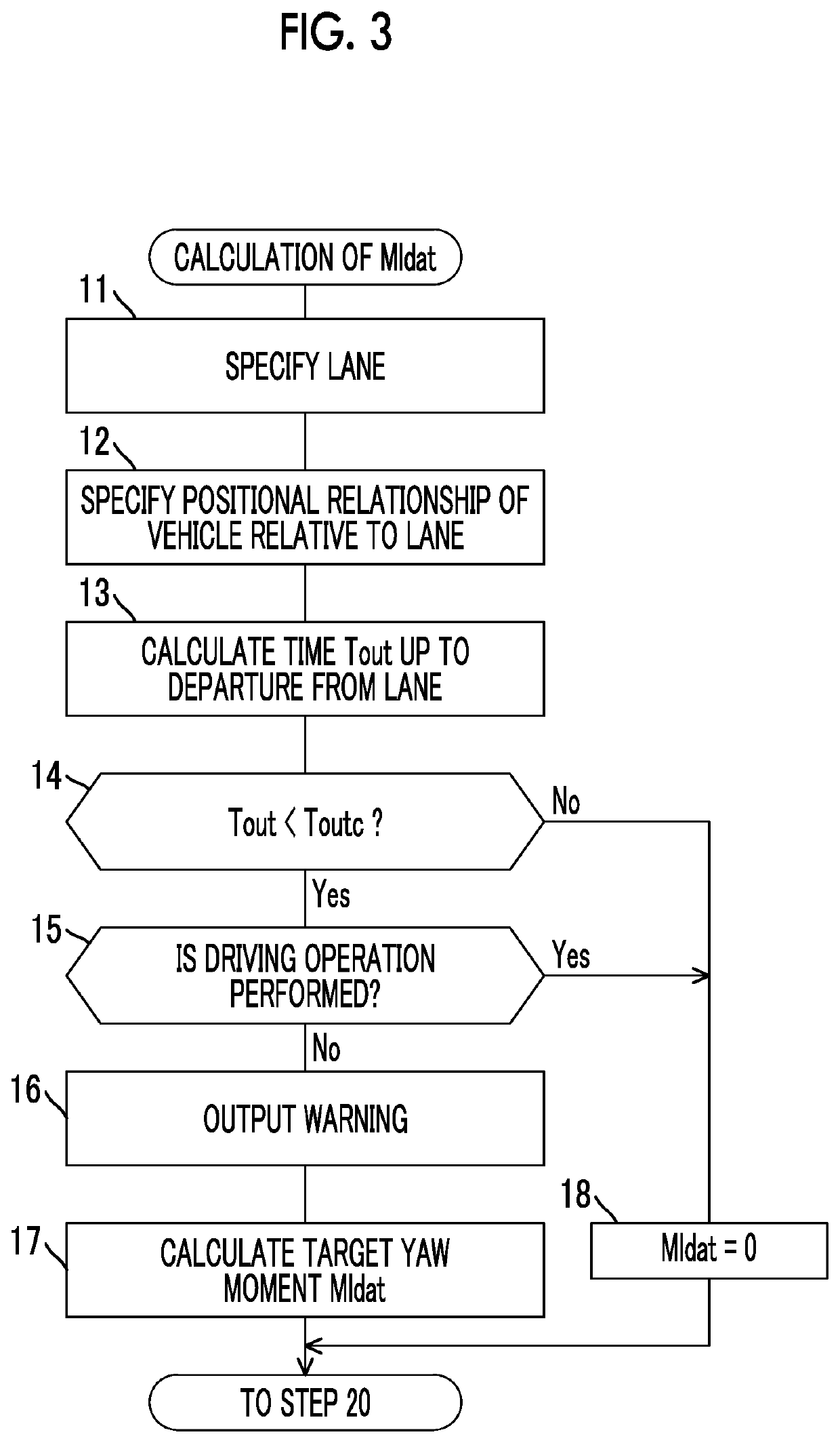
[0141]In a second embodiment, the lane departure prevention control is performed in the same way as in the first embodiment in accordance with the flowcharts illustrated in FIGS. 2 and 3 except for Steps 100 and 140.

[0142]In Step 100 in the second embodiment, similarly to the first embodiment, the target yaw moment Mpst, the phase-compensated normative yaw rate Yrvcf of the vehicle, and the phase-compensated normative lateral acceleration Gyvcf of the vehicle are calculated. The yaw rate Yr and the lateral acceleration Gy of the vehicle detected by the yaw rate sensor 70 and the lateral acceleration sensor 68 are stored as a reference value Yrr of the yaw rate and a reference value Gyr of the lateral acceleration in the RAM.

[0143]In Step 140, an end reference value ΔYre of the yaw rate is calculated with reference to the map illustrated in FIG. 10 based on the reference value Yrr of the yaw rate. An end reference value ΔGye of the lateral acceleration is calculated with reference to...

third embodiment

[0145]In a third embodiment, the lane departure prevention control is performed in the same way as in the first embodiment in accordance with the flowcharts illustrated in FIGS. 2 and 3 except for Steps 100 and 140.

[0146]In Step 100 in the third embodiment, the target yaw rate Yrnf is calculated by Equation (2) or (4). The target spin prevention yaw moment Mpst is calculated with reference to the map illustrated in FIG. 12 based on the difference ΔYr (=Yrnf−Yr) between the target yaw rate Yrnf and the actual yaw rate Yr. Similar to the first and second embodiments, the phase-compensated normative yaw rate Yrvcf of the vehicle and the phase-compensated normative lateral acceleration Gyvcf of the vehicle are also calculated.

[0147]In Step 140, for example, when all the above-mentioned conditions (G) and (H) and the following condition (K) are satisfied, it may be determined that the end conditions are satisfied. Condition (G) may be omitted when Condition (A) is omitted, or Condition (...


PUM


Abstract

A lane departure prevention system includes a controller configured to control a braking force of vehicle wheels such that a lane departure prevention yaw moment is applied to a vehicle. The controller determines whether there is a likelihood that the vehicle enters a spinning state based on at least one of a difference between an actual yaw rate and a normative yaw rate of the vehicle calculated based on a steering angle, a vehicle speed, and the lane departure prevention yaw moment, and a degree of braking slip of a turning inside wheel when the lane departure prevention yaw moment is a yaw moment for preventing departure of the vehicle from a lane to a turning outside, and applies a spin prevention yaw moment to the vehicle when it is determined that there is a likelihood that the vehicle will enter the spinning state.

Description

INCORPORATION BY REFERENCE[0001]This is a Continuation of application Ser. No. 15 / 792,149 filed Oct. 24, 2017, which claims the benefit of Japanese Priority Application No. 2016-220707 filed Nov. 11, 2016. The disclosure of each of the prior applications is hereby incorporated by reference herein in its entirety.BACKGROUND1. Technical Field[0002]The disclosure relates to a lane departure prevention system of a vehicle such as an automobile.2. Description of Related Art[0003]A lane departure prevention system configured to generate a lane departure prevention yaw moment for preventing a vehicle from departing from a traveling lane using a braking force difference between right and left wheels when it is determined that there is concern that the vehicle will depart from the traveling lane based on a positional relationship of the vehicle relative to the traveling lane has already been practically implemented. An example of the lane departure prevention system is described in Japanese ...

Claims


Application Information

Patent Timeline
Patent Type & Authority Applications(United States)
IPC IPC(8): B60T8/1755B60T7/12B60W30/12B60W30/02B60T8/00B60T8/58B60T8/171
CPCB60W30/02B60W2540/18B60W2520/14B60T7/12B60W2720/406B60T2250/03B60T8/17557B60W30/12B60W2720/14B60W2710/18B60T2201/083B60T8/171B60T8/00B60W2520/20B60T8/58B60T8/17552B60W2520/10B60W10/184B60W2520/125
Inventor MITSUMOTO, HISANORI
Owner TOYOTA JIDOSHA KK
Features
  • Generate Ideas
  • Intellectual Property
  • Life Sciences
  • Materials
  • Tech Scout
  • Unparalleled Data Quality
  • Higher Quality Content
  • 60% Fewer Hallucinations
Learn More