Thin-slotting lifting synchronous grouting device and its usage method

a grouting device and synchronous technology, applied in the field of spraying, can solve the problems of large amount of embankment design and construction, large amount of embankment aging, prominent seepage problem, etc., and achieve the effect of less friction, less amount of impermeable raw materials, and small disturbance of soil mass

Active Publication Date: 2020-08-13
INFRASTRUCTURE RENEWAL INST OF SOUTHERN CHINA +1
View PDF0 Cites 5 Cited by
  • Summary
  • Abstract
  • Description
  • Claims
  • Application Information

AI Technical Summary

Benefits of technology

[0006]To overcome the shortcomings mentioned above, a thin-slotting lifting synchronous grouting device and its usage method are provided in this invention. The present invention combines slotting with grouting and it has a small disturbance to soil mass. The device suffers less friction. Compared with the traditional anti-seepage technologies, the technology presented in this invention consumes a less amount of impermeable raw materials, which greatly lowers the construction cost. Moreover, the present invention provides the matched equipment and construction technology for the thin anti-seepage walls, and it is able to be applied in the thin-slotting of various projects, showing great economic and social benefits and wide development and application prospects.
[0026]Secondly, the technology presented in this invention is cost-saving. Since the cutting plates are thin and they are with a thickness of 20-50 mm, the formed slots are with the same thickness. Compared with the traditional anti-seepage wall constructing technologies, the present invention consumes a less amount of impermeable materials, which can greatly lower the construction cost.
[0027]Thirdly, the technology presented in this invention brings little disturbance to the soil mass. Due to the thin cutting plates, the friction force of the device against the soil mass is small, and thus the soil mass is little disturbed. The slotting process is convenient and fast. The technology presented in invention adopts the dry construction method and no slurry is needed for preventing the walls from deformation, and thus it has little influence on the surrounding environment.

Problems solved by technology

Limited by the previous economic and technical conditions, the design and construction of a large amount of embankments have inherent deficiencies.
After a long period of operation and disrepair, these embankments are seriously aging and have the prominent seepage problem; particularly, the soil embankments are threatened by different seepage hazards.
Due to the non-standard preliminary design and construction, most of the landfill sites are not adequately impermeable that a lot of landfill leachate without any processing will directly penetrate into the soil and underground water, resulting in serious pollutions to the environment.
To be specific, the conventional anti-seepage wall building technologies are to form the impervious body in soil through slotting, stirring, spraying and vibrating independently, which has great disturbance and damage to the embankments, and they have a long construction period, and they are expensive and inconvenient.
Especially for the small embankments, the current technologies are useless because it is difficult to place the relevant equipment on the construction sites as the equipment is always too large in their size.

Method used


Image

  • Thin-slotting lifting synchronous grouting device and its usage method

Examples


Embodiment Construction

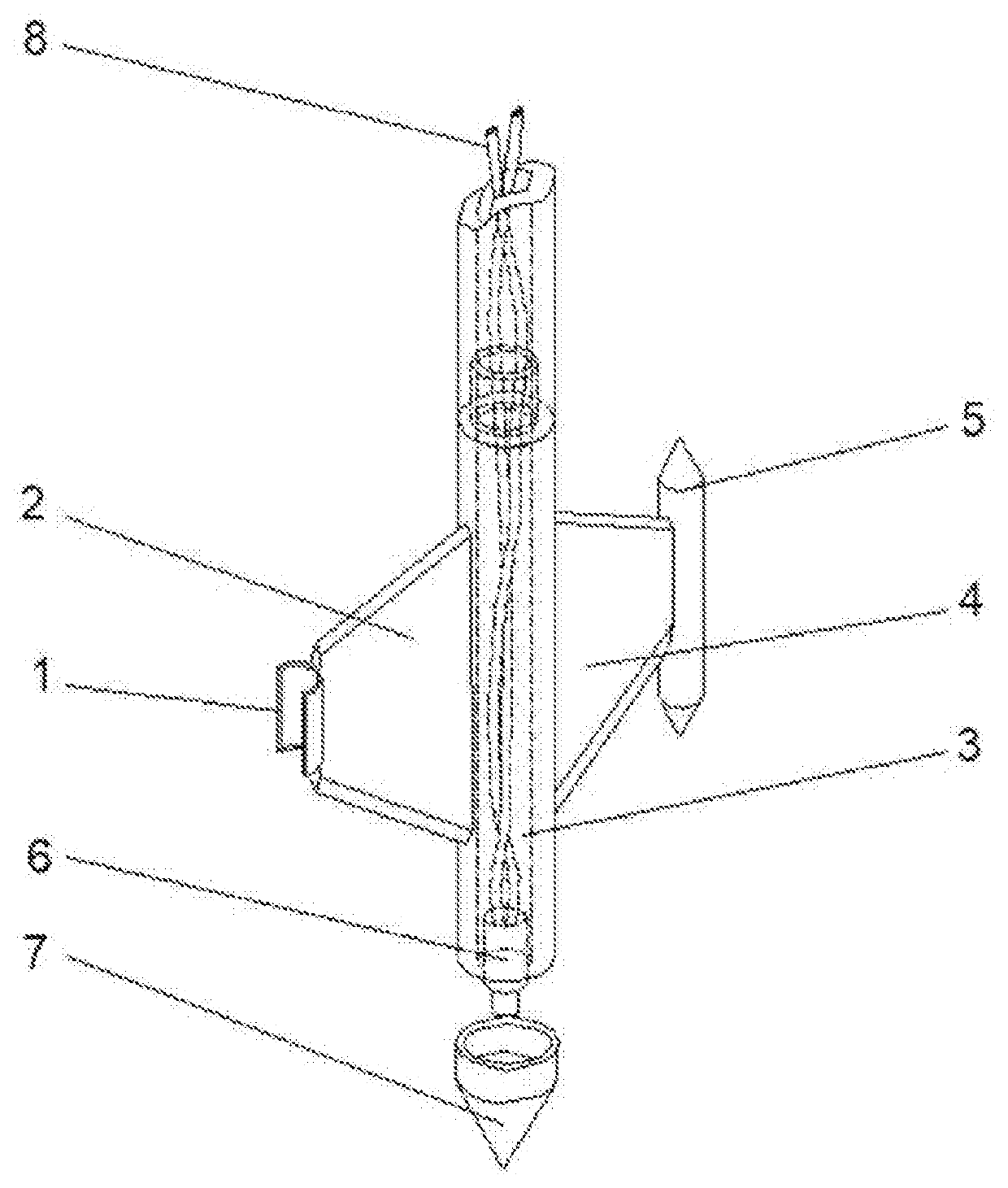
[0030]As shown in the FIGURE, the thin-slotting lifting synchronous grouting device provided in this invention comprises a hollow force-beating column 3, through which a feeding pipe 8 passes; a left cutting plate 2 and a right cutting plate 4 are respectively fixedly arranged on each side of the hollow force-bearing column 3 along the axial direction thereof; a left connecting plate 1 socketing with a first drill pipe is fixedly arranged on the outside of the left cutting plate 2; a right guiding column 5 is fixedly arranged on the outside of the tight cutting plate 4; the center lines of the left connecting plate 1, the right guiding column 5 and the hollow force-bearing column 3 are in a same plane; the top end of the feeding pipe 8 is connected to a grouting device; the bottom end of the feeding pipe 8 is connected to a spraying device 6; a spraying nozzle of the spraying device 6 stretches out along the hollow force-bearing column 3; and the lower end of the hollow force-hearin...


PUM


Abstract

A thin-slotting lifting synchronous grouting device and its usage method are provided, The device includes a hollow force-bearing column through which a feeding pipe passes; wherein: left and right cutting plates are respectively fixedly arranged on each side of the hollow force-bearing column; a left connecting plate is fixedly arranged on an outside of the left cutting plate; a right guiding column is fixedly arranged on an outside of the right cutting plate; center lines of the left connecting plate, the right guiding column and the hollow force-bearing column are in a same plane; a top end of to the feeding pipe is connected to a grouting device, and a bottom end is connected to a spraying device; a spraying nozzle of the spraying device stretches out along the hollow force-bearing column; and a lower end of the hollow force-bearing column is connected with a disposable conical head.

Description

CROSS REFERENCE OF RELATED APPLICATION[0001]The application claims priority under 35 U.S.C. 119(a-d) to CN 201910818543.7, filed Aug. 30, 2019.BACKGROUND OF THE PRESENT INVENTIONField of Invention[0002]The present invention relates to a technical field of slotting and spraying for constructing an anti-seepage layer at various infrastructures such as soil embankments, waste landfills, buildings, and more particularly to a thin-slotting lifting synchronous grouting device and its usage method.Description of Related Arts[0003]In China, the embankment projects of rivers, lakes and seas reach a length of tens of thousands of kilometers. The embankments have the flood control and disaster prevention effects and they play an important role in guaranteeing the safety of the flood control works in China. The strong embankments work as barriers that keep the flood at the outer side to avoid the damages of the flood to the life and property safety of the nearby residents. Limited by the previo...

Claims


Application Information

Patent Timeline
Patent Type & Authority Applications(United States)
IPC IPC(8): E02D15/04E02D3/12
CPCE02D3/12E02D15/04E02D2250/003E02D2250/0023
Inventor WANG, FUMINGFANG, HONGYUANZHAO, PENGPAN, YANHUIZHAO, XIANFENGWANG, YINGLI
Owner INFRASTRUCTURE RENEWAL INST OF SOUTHERN CHINA
Why Eureka
Try Eureka