Method and system for particle characterization and identification
What is AI technical title?
AI technical title is built by PatSnap AI team. It summarizes the technical point description of the patent document.
a particle characterization and particle technology, applied in the field of optical sensors, can solve the problem of imposing additional limits on the allowable pressure and temperature rang
Active Publication Date: 2020-08-13
HAL TECH LLC
View PDF0 Cites 3 Cited by
Summary
Abstract
Description
Claims
Application Information
AI Technical Summary
This helps you quickly interpret patents by identifying the three key elements:
Problems solved by technology
Method used
Benefits of technology
Benefits of technology
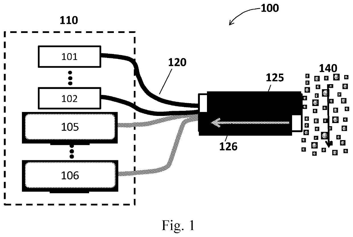
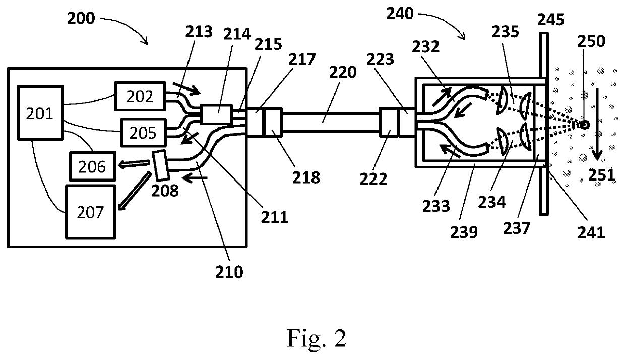
The invention is a system for identifying and characterizing particles using light scattering techniques. The system includes a sensor probe with optical components that can manipulate and detect light in a gaseous or liquid media. The sensor probe can withstand harsh environments and has the capability to measure particle size, size distribution, and mass concentrations. The system also includes an electro-optical unit that converts light into electrical signals and performs signalprocessing. The invention allows for the use of multiple light sources and detectors to measure the same particles from different angles, resulting in more accurate particle characterization.
Problems solved by technology
The method used to fix the components together may impose additional limits on the allowable pressure and temperature range.
Method used
Image
Click on the blue label to locate the original text in one second.
Reading with bidirectional positioning of images and text.
Examples
Embodiment Construction
[0024]The above, as well as other objects and advantages of this disclosure, will become readily apparent to those skilled in the art from reading the following description of an embodiment of the invention. The description and drawings illustrate exemplary embodiments of the invention and serve to enable one skilled in the art to make or use the invention and are not intended to limit the scope of the invention in any manner. With respect to the methods disclosed and illustrated, the steps presented are exemplary in nature, and thus, the order of the steps is not necessary or critical.
[0025]As used herein, the terms “first”, “second”, “third”, and “fourth” may be used interchangeably to distinguish one component from another and are not intended to signify location or importance of the individual components.
[0026]The present disclosure uses an in-situ approach wherein a sensor probe separates the light source(s), detector(s), and electronics from the harsh measurement zone by using...
PUM
Abstract
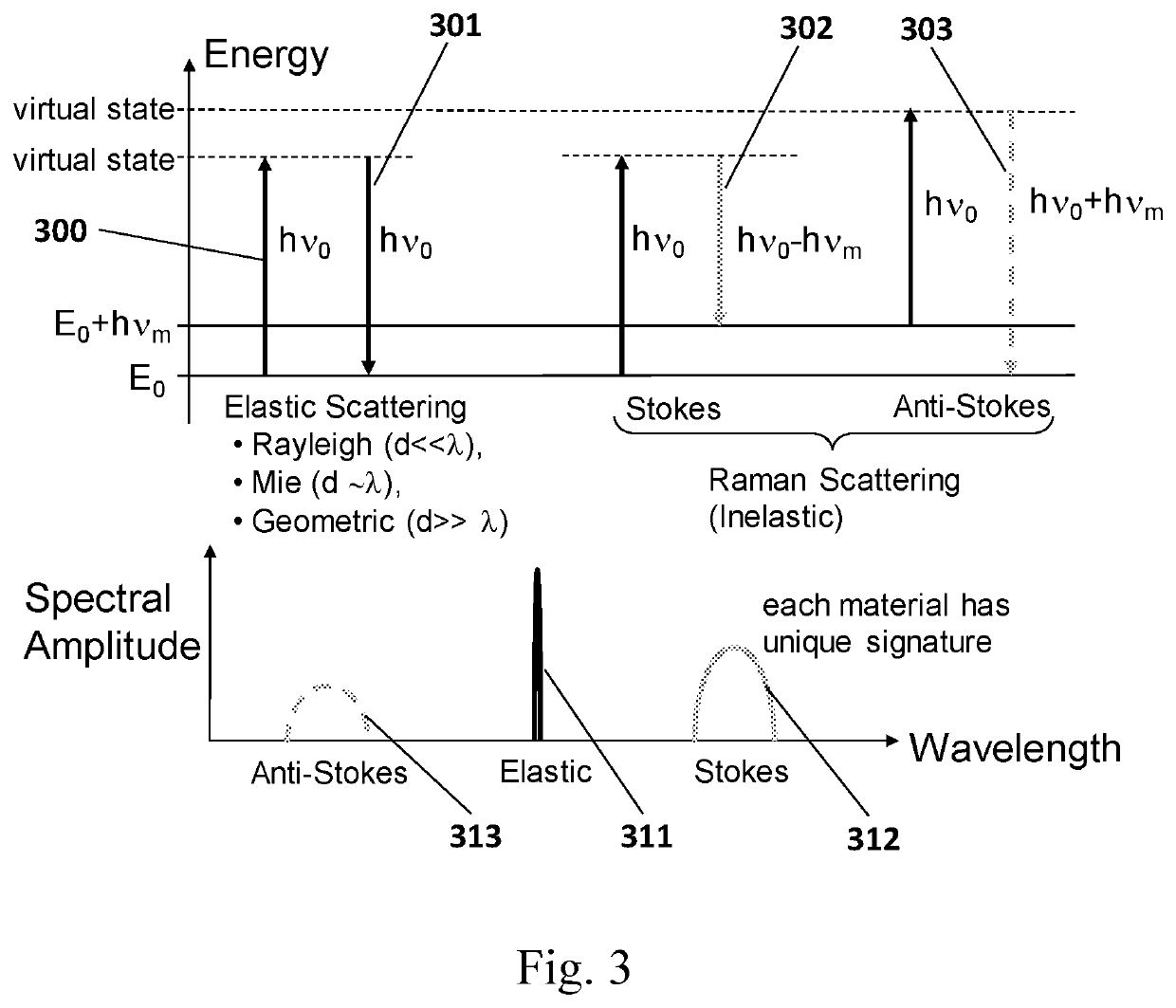
Disclosed herein is a novel, compact optical particle identification and characterization system and method of use within both gaseous and liquid media. The system can implement both elastic and inelastic light scattering techniques simultaneously under the same sensor platform. By separating the sensing components from the electro-optical unit and using optical fibers for interconnection, only the sensing components need to be exposed to the environmental conditions. This reduces the design constraints on the electro-optical unit and permits the incorporation of optical components into the sensing probe that can withstand high-temperature, high-pressure, and corrosive environments. Thus, the system can be used in benign, moderate, and harsh environments.
Description
GOVERNMENT RIGHTS[0001]The invention described herein was made under U.S. Navy contract numbers N68335-14-C-0080, N68335-16-C-0499, and N68335-18-C-0388. The government may have rights under this invention.REFERENCES CITED[0002]U.S. Patent DocumentsDocument NumberDateNameUS ClassificationU.S. Pat. No. 10,139,329 B2November 2018OwenU.S. Pat. No. 9,714,967 B1July 2017Weickert et al.324 / 456US-2016 / 0313233 A1October 2016Zangmeister et al.356 / 416US-2010 / 0288921 A1November 2010Wang et al.250 / 287U.S. Pat. No. 7,675,619 B2March 2010Danehy et al.356 / 337U.S. Pat. No. 7,518,719 B2April 2009Sprenger et al 356 / 243.2US-2009 / 0039249 A1February 2009Wang et al.250 / 287U.S. Pat. No. 7,404,929 B2July 2008Fulghum, Jr. 422 / 82.05U.S. Pat. No. 7,260,483 B2August 2007Gard et al.702 / 22 U.S. Pat. No. 7,106,442 B2September 2006Silcott et al.356 / 338U.S. Pat. No. 7,072,038 B2July 2006Quist et al.356 / 338U.S. Pat. No. 6,490,040 B1December 2002Berthold356 / 342U.S. Pat. No. 6,321,608 B1November 2001Wagner et al. 73...
Claims
Application Information
Patent Timeline
Application Date:The date an application was filed.
Publication Date:The date a patent or application was officially published.
First Publication Date:The earliest publication date of a patent with the same application number.
Issue Date:Publication date of the patent grant document.
PCT Entry Date:The Entry date of PCT National Phase.
Estimated Expiry Date:The statutory expiry date of a patent right according to the Patent Law, and it is the longest term of protection that the patent right can achieve without the termination of the patent right due to other reasons(Term extension factor has been taken into account ).
Invalid Date:Actual expiry date is based on effective date or publication date of legal transaction data of invalid patent.

