Driving circuit for display panel and high voltage tolerant circuit
a driving circuit and high voltage tolerant technology, applied in the direction of electronic switching, pulse technique, instruments, etc., can solve the problem that the solution cannot meet the high standard of liquid crystal display
- Summary
- Abstract
- Description
- Claims
- Application Information
AI Technical Summary
Benefits of technology
Problems solved by technology
Method used
Image
Examples
first embodiment
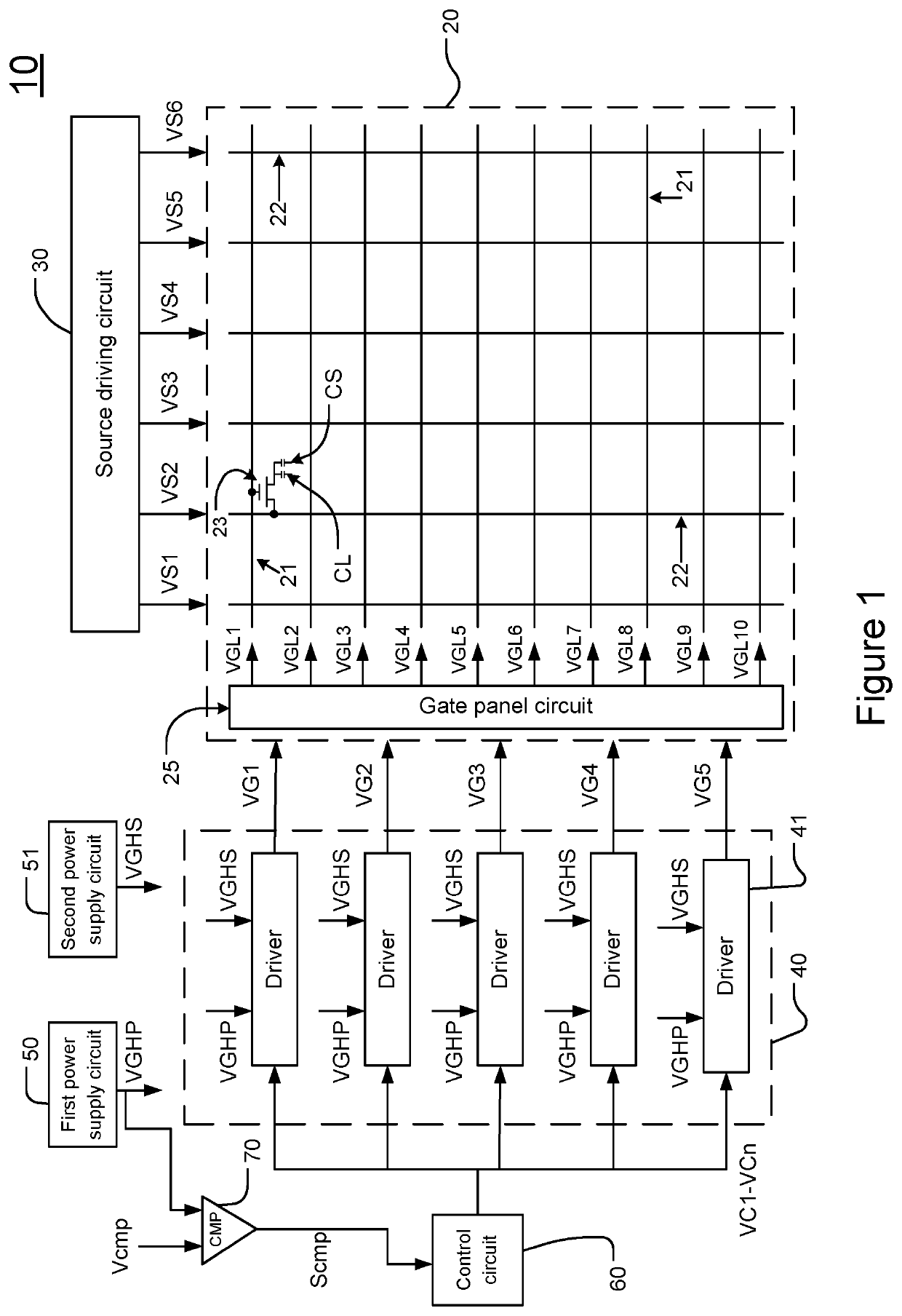
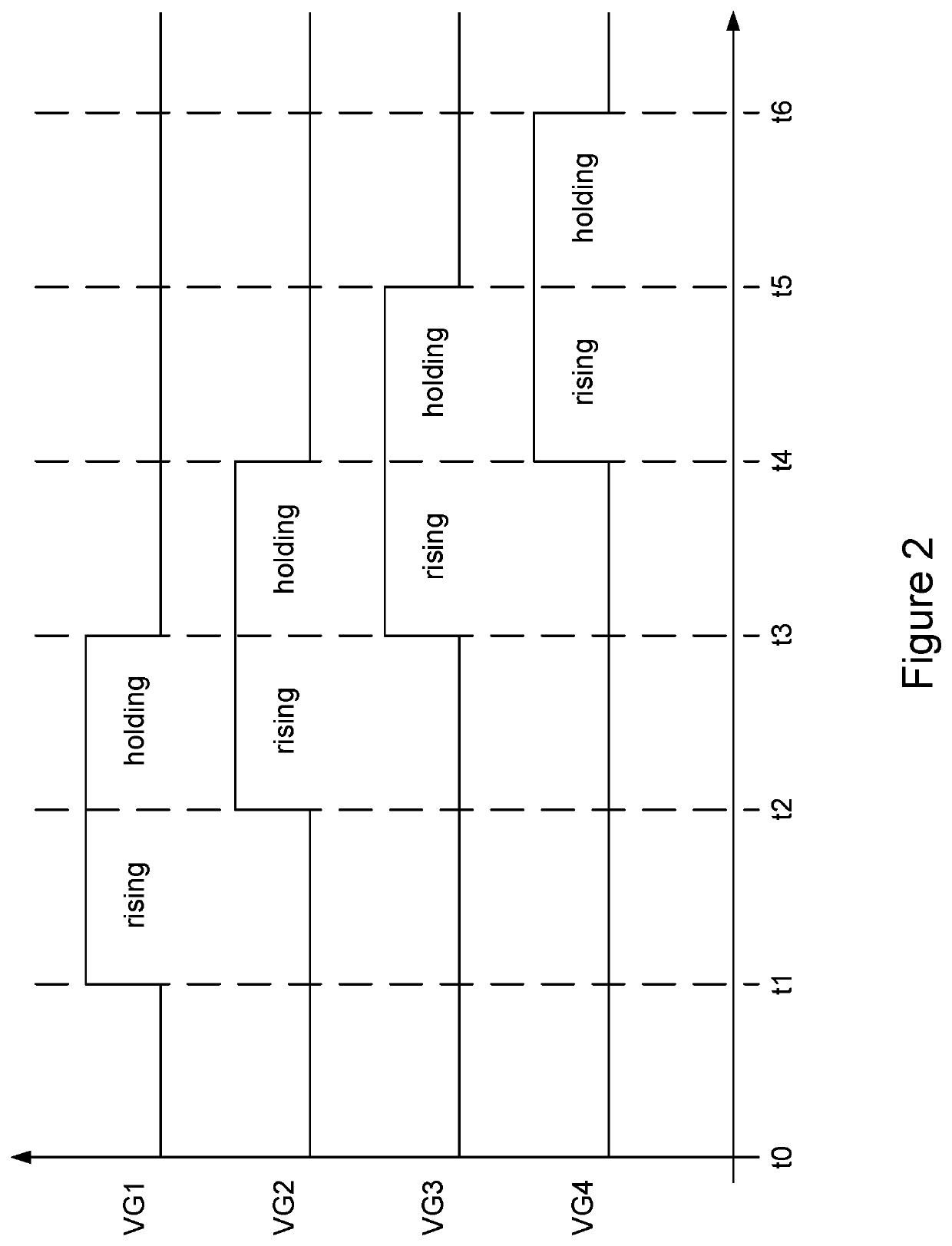
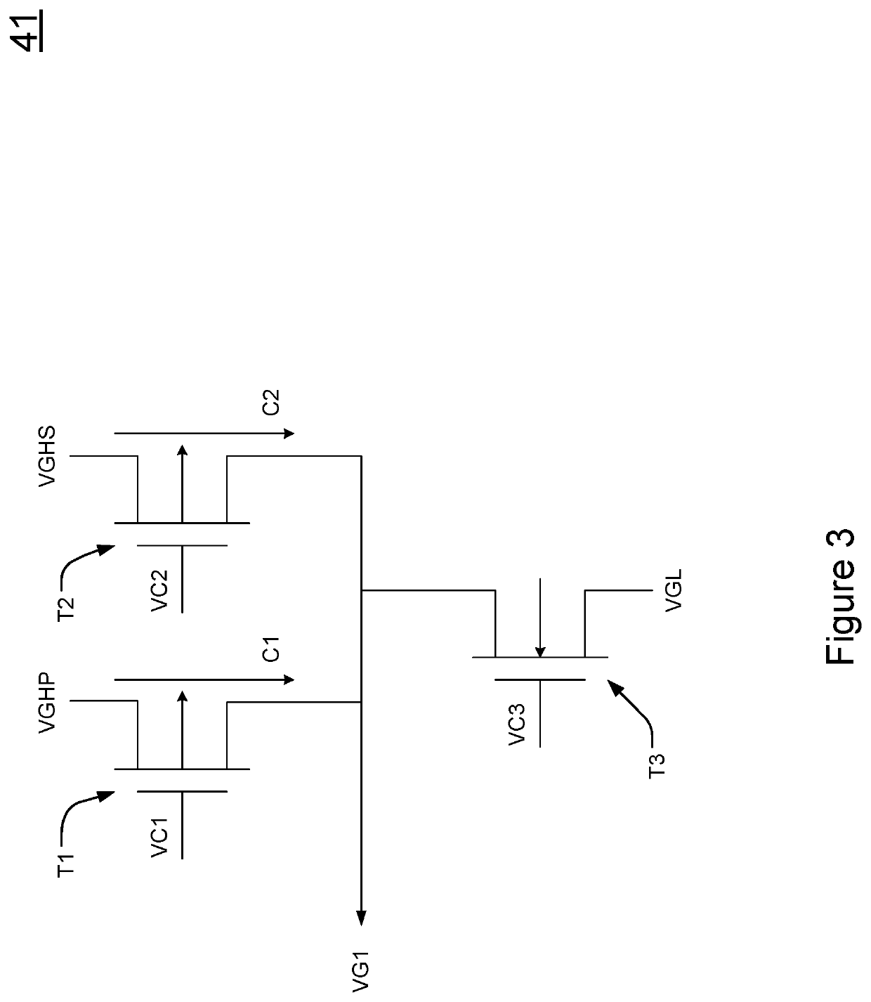
[0025]Please refer to FIG. 3, which shows a circuit diagram of the driver according to the present invention. As shown in the figure, the driver 41 includes a plurality of transistors T1, T2, T3. An input terminal of the transistor T1 is coupled to the first power supply circuit 50 and receives the first supply voltage VGHP. The input terminal of the transistor T1 is a first power supply input terminal of the driver 41. A control terminal of the transistor T1 is coupled to the control circuit 60 for receiving the control signal VC1. An output terminal of the transistor T1 is coupled to an output terminal of the driver 41. After the control circuit 60 outputs the control signal VC1 and controls the transistor T1 to turn on, the transistor T1 transmits the first supply voltage VGHP to the output terminal of the driver 41 for rising the voltage level of the gate signal VG1 to the voltage level of the first supply voltage VGHP in the voltage rising period rising. The input and output te...
second embodiment
[0030]Please refer to FIG. 4, which shows a circuit diagram of the driver according to the present invention. As shown in the figure, to save the power consumption of the gate signal VG1 in the voltage rising period rising, the driver 41 can include a precharge circuit 42, which includes a high voltage device such as a high voltage tolerant transistor T4. The precharge circuit 42 is coupled to the output terminal of the driver 41 for outputting a precharge voltage to the output terminal of the driver 41. Thereby, the gate signal VG1 can be precharged to the voltage level of the precharge voltage before being charged to the voltage level of the first supply voltage VGHP. The embodiment in FIG. 4 includes a third power supply circuit 52, which is capable of outputting precharge voltages with different levels, namely, a first precharge voltage V1 and a second precharge voltage V2 in the embodiment in FIG. 4. The third power supply circuit 52 receives and outputs the first precharge vol...
third embodiment
[0032]Please refer to FIG. 5, which shows a circuit diagram of the driver according to the present invention. As shown in the figure, the precharge circuit 43 in the embodiment in FIG. 5 replaces the precharge circuit 42 in the embodiment in FIG. 4. The difference therebetween is that the precharge circuit 43 in FIG. 5 includes a plurality of transistors. The gate across the body of the plurality of transistors can tolerate medium voltages, while the source across the drain can tolerate high voltages. Thereby, the present invention can be applied to applications requiring tolerance of high voltages. The precharge circuit 42 in FIG. 4 includes one or more high voltage tolerant transistor T4. The precharge circuit 43 includes a plurality of transistors T5, T6, T7, T8, D1. The transistors T5, T6, D1, T7, T8 are a first switching device, a second switching device, a control device, a third switching device, and a fourth switching device of the precharge circuit 43. Thereby, the first sw...
PUM
 Abstract
Description
Claims
Application Information
 - R&D
- Intellectual Property
- Life Sciences
- Materials
- Tech Scout
- Unparalleled Data Quality
- Higher Quality Content
- 60% Fewer Hallucinations
Browse by: Latest US Patents, China's latest patents, Technical Efficacy Thesaurus, Application Domain, Technology Topic, Popular Technical Reports.
© 2025 PatSnap. All rights reserved.Legal|Privacy policy|Modern Slavery Act Transparency Statement|Sitemap|About US| Contact US: help@patsnap.com


