Carry-signal controlled LED light with fast discharge and LED light string having the same
a technology of led light and led light string, which is applied in the direction of electrical equipment, etc., can solve the problems of increasing the capacitance of the led light string, increasing the possibility of incorrectly determining the light signal, and the speed of the system processing the signals is not fast enough
- Summary
- Abstract
- Description
- Claims
- Application Information
AI Technical Summary
Benefits of technology
Problems solved by technology
Method used
Image
Examples
second embodiment
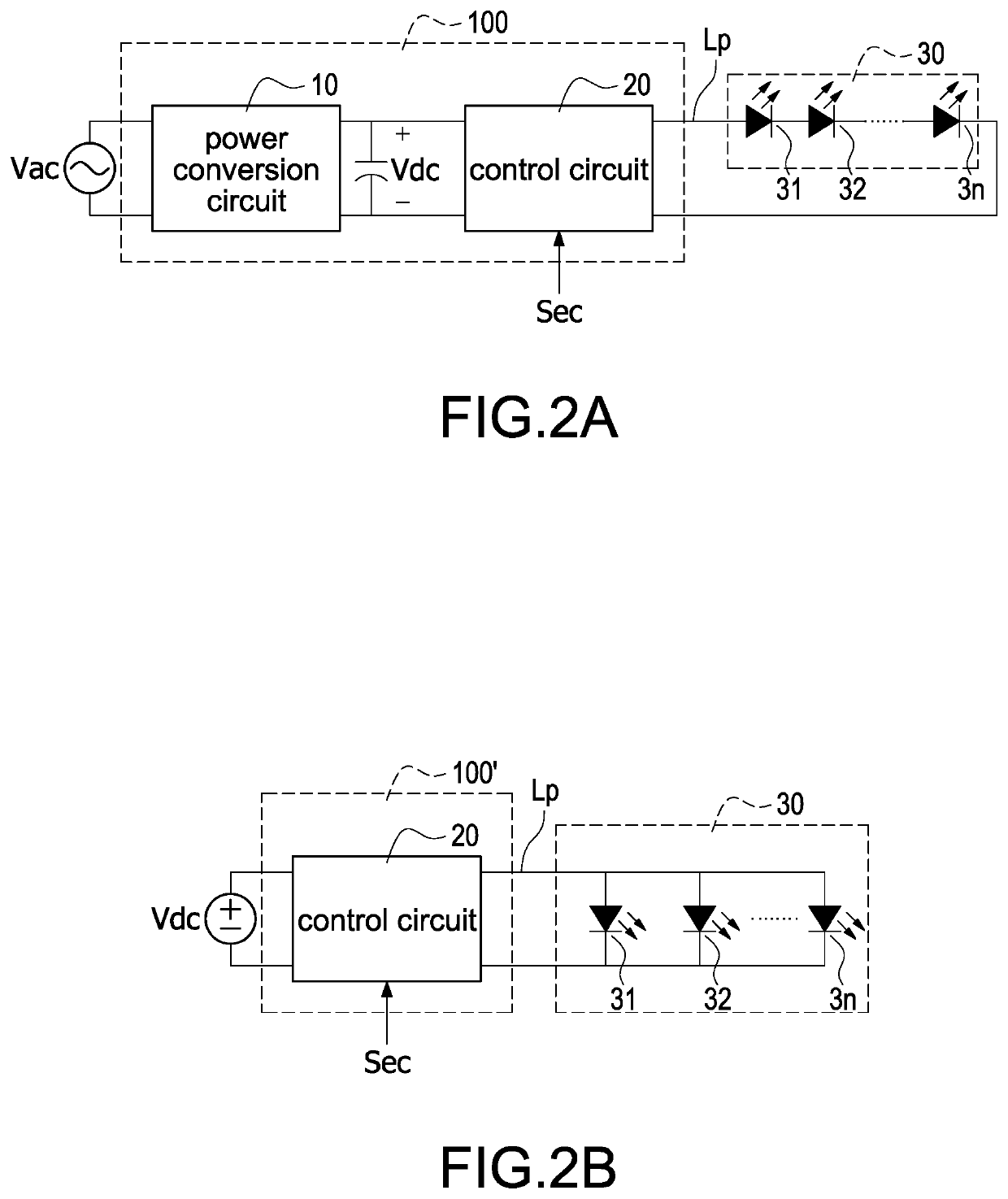
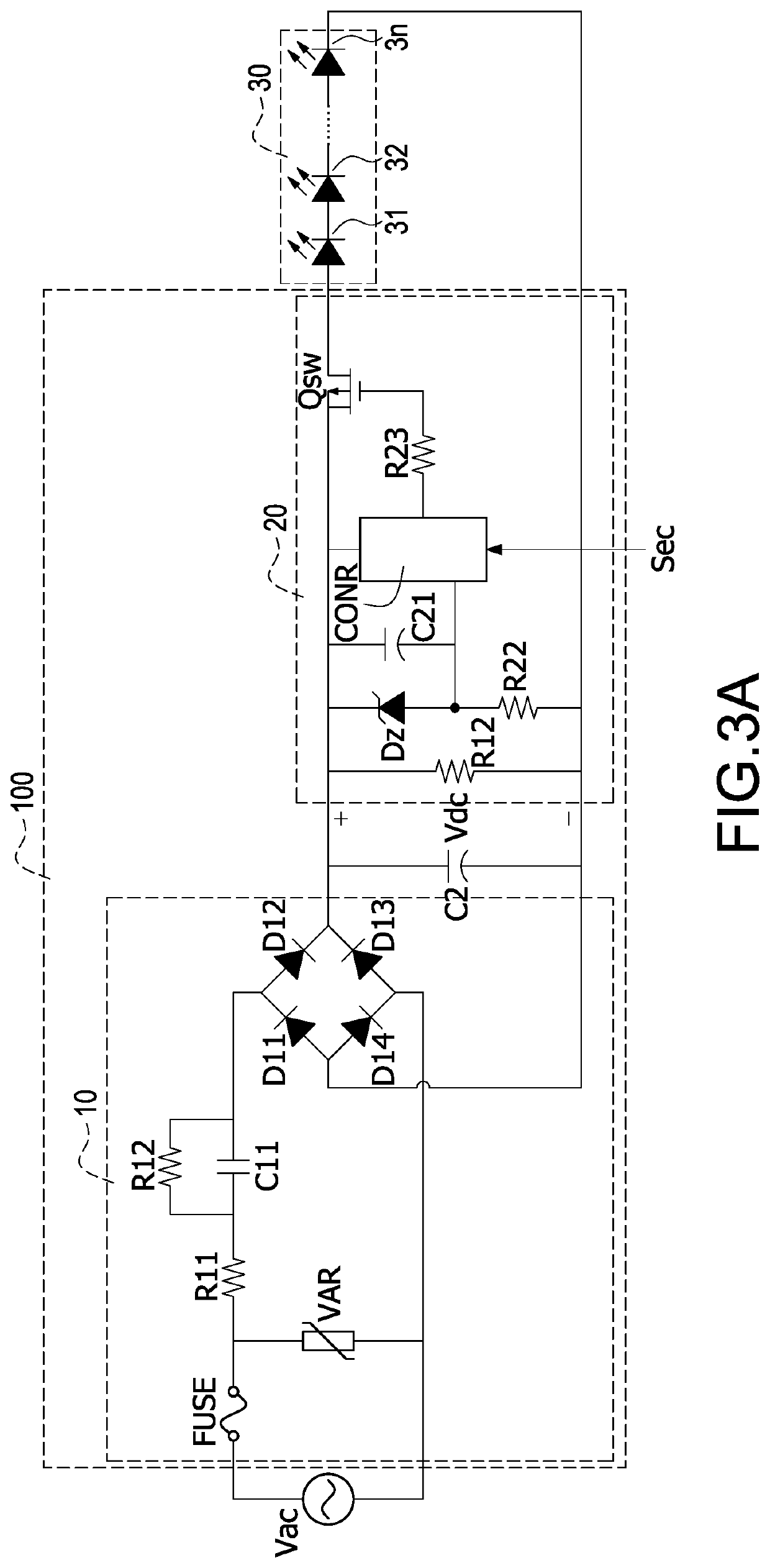
[0049]Please refer to FIG. 3C, which shows a detailed circuit diagram of the power conversion circuit and the control circuit in FIG. 2A. In comparison with FIG. 3A, the control circuit 20 further includes a voltage adjust unit 24. The voltage adjust unit 24 can be a fast discharge circuit for fast discharging the DC working power to supply the LED light string 30. Alternatively, the voltage adjust unit 24 is a voltage adjust capacitor for slowly discharging the DC working power to supply the LED light string 30.
[0050]If the voltage adjust unit 24 is the voltage adjust capacitor, the voltage adjust unit 24 is coupled in parallel to the LED light string 30 for slowly discharging the DC working power to supply the LED light string 30 according to the capacitance value of the voltage adjust capacitor.
[0051]If the voltage adjust unit 24 is the fast discharging circuit, the voltage adjust unit 24 is coupled to the output control switch Qsw, the LED light string 30, and the control unit ...
first embodiment
[0065]Please refer to FIG. 4B to FIG. 4D, which show block circuit diagrams of three specific circuits of the LED module according to the present disclosure. In FIG. 4B, the fast discharge unit 55 is implemented by a resistor 551. Two ends of the resistor 551 are coupled to two ends of the voltage stabilizer 41, and the power consumption of the resistor 551 can reduce the voltage level of the light control signal. Specifically, when the resistance of the resistor 551 is larger, the voltage level decreases faster; on the contrary, when the resistance of the resistor 551 is smaller, the voltage level decreases slowly. Therefore, the effect of fast discharge can be achieved.
[0066]In FIG. 4C, the fast discharge unit 55 is implemented by a series-connected structure composed of a resistor 551 and a transistor 552 coupled in series to the resistor 551. Two ends of the series-connected structure are coupled at two ends of the voltage stabilizer 41, and a gate of the transistor 552 is coupl...
PUM
 Abstract
Description
Claims
Application Information
 - R&D
- Intellectual Property
- Life Sciences
- Materials
- Tech Scout
- Unparalleled Data Quality
- Higher Quality Content
- 60% Fewer Hallucinations
Browse by: Latest US Patents, China's latest patents, Technical Efficacy Thesaurus, Application Domain, Technology Topic, Popular Technical Reports.
© 2025 PatSnap. All rights reserved.Legal|Privacy policy|Modern Slavery Act Transparency Statement|Sitemap|About US| Contact US: help@patsnap.com


