
Station communications over electrical transmission lines

a technology of electrical transmission lines and substations, applied in relays, power distribution line transmission, transportation and packaging, etc., can solve the problems of ineffective use of power transmission lines between substations as a medium for broadband communication, high cost of high cost of older technologies such as pilot wires using copper telephone wires, etc., to achieve greater administrative control, low cost, and the effect of adding functionality

Active Publication Date: 2012-07-03
GRIDEDGE NETWORKS
View PDF11 Cites 0 Cited by
  • Summary
  • Abstract
  • Description
  • Claims
  • Application Information

AI Technical Summary

Benefits of technology

"The invention is a new method of using a high-speed communication technology called Broadband over Powerline (BPL) to connect substations in a power grid. BPL uses the electrical grid as a communication medium, which is cheaper and more convenient than using fiber optic cables or wireless networks. It also allows for faster data rates and better protection against cyber and physical security threats. The invention addresses the need for better communication between substations and enables new smart grid applications. It uses a combination of fiber and BPL to provide high-speed internet to unconnected or partially connected stations. The invention also includes techniques to protect the BPL signal from electrical noise and improve system performance. Overall, the invention provides a cost-effective and efficient solution for connecting substations in a power grid."

Problems solved by technology

As of yet, there has been no effective use of power transmission lines between substations as a medium for broadband communications.
Older technologies, such as pilot wire using copper telephone wires are very expensive and are being phased out by the wireline telephone companies.
Both of these options are labor intensive, time-consuming and very expensive.
In some cases, the utility has to negotiate right-of-way permits before the work can commence, a process that can take months or even years to conclude.

Method used


Image

  • Station communications over electrical transmission lines
  • Station communications over electrical transmission lines
  • Station communications over electrical transmission lines

Examples


implementation embodiment

[0088]The present invention can be implemented in various embodiments, such as (but not limited to) the embodiments described below, as well as those previously discussed.

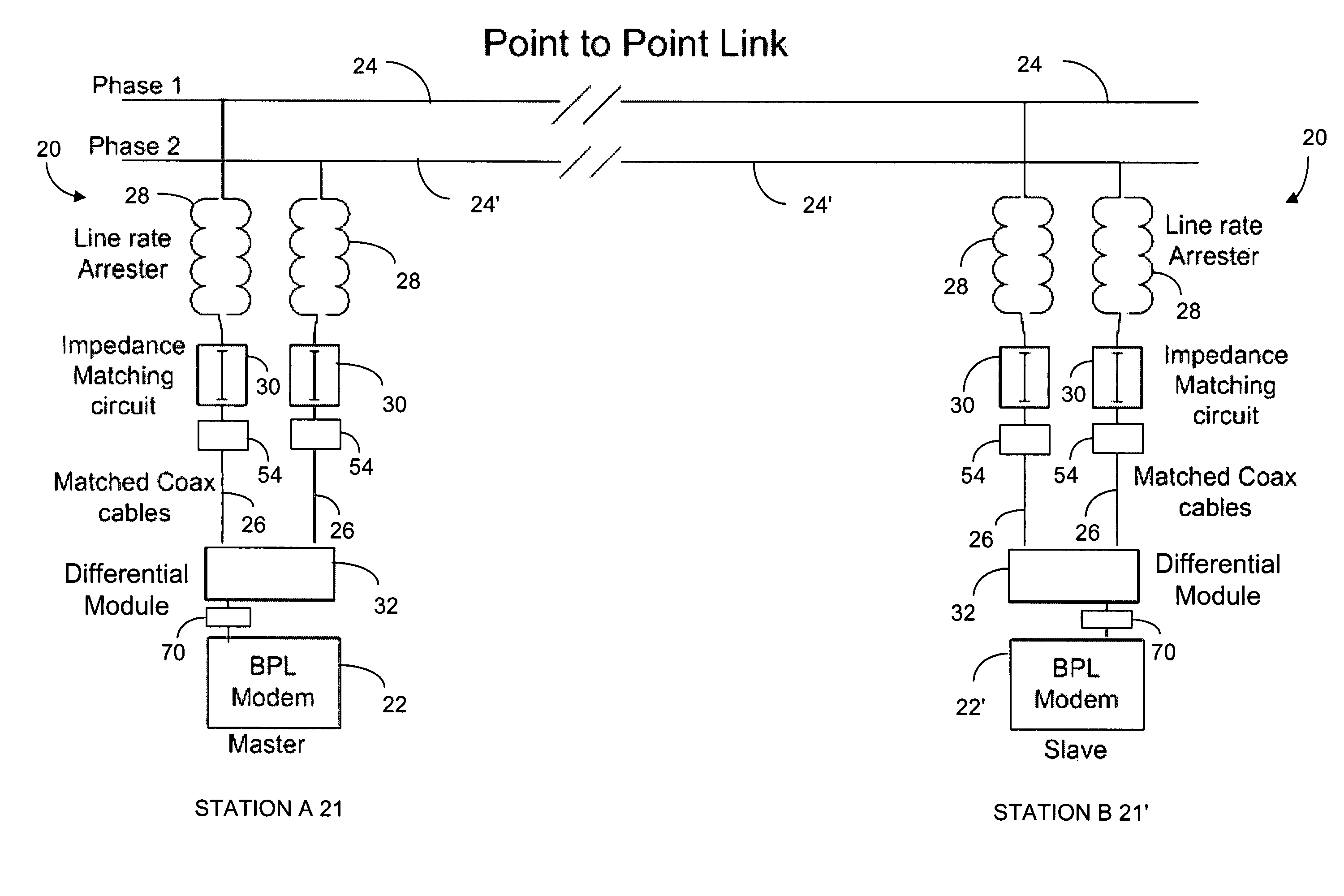
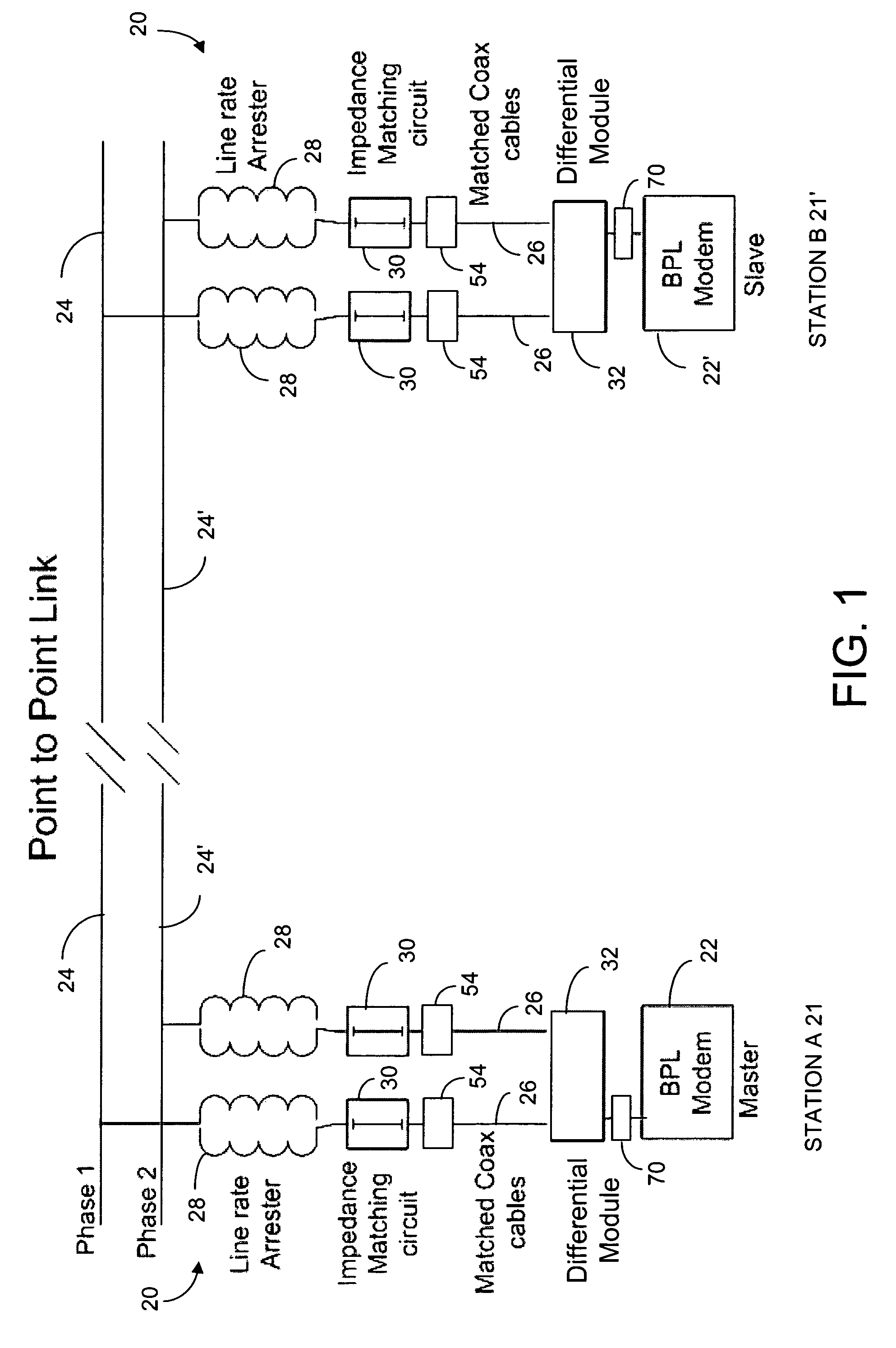
[0089]A first embodiment of the present invention is a method and a system for station to station and station to control center communications over electric transmission lines using BPL technology and named HVBPL. Each communications system can use one or two BPL modems. A modem can be used as FDM master, as FDM slave or as a TDM repeater. BPL modems operate in the range of 1 MHz to 50 MHz (see FIGS. 1 and 3).

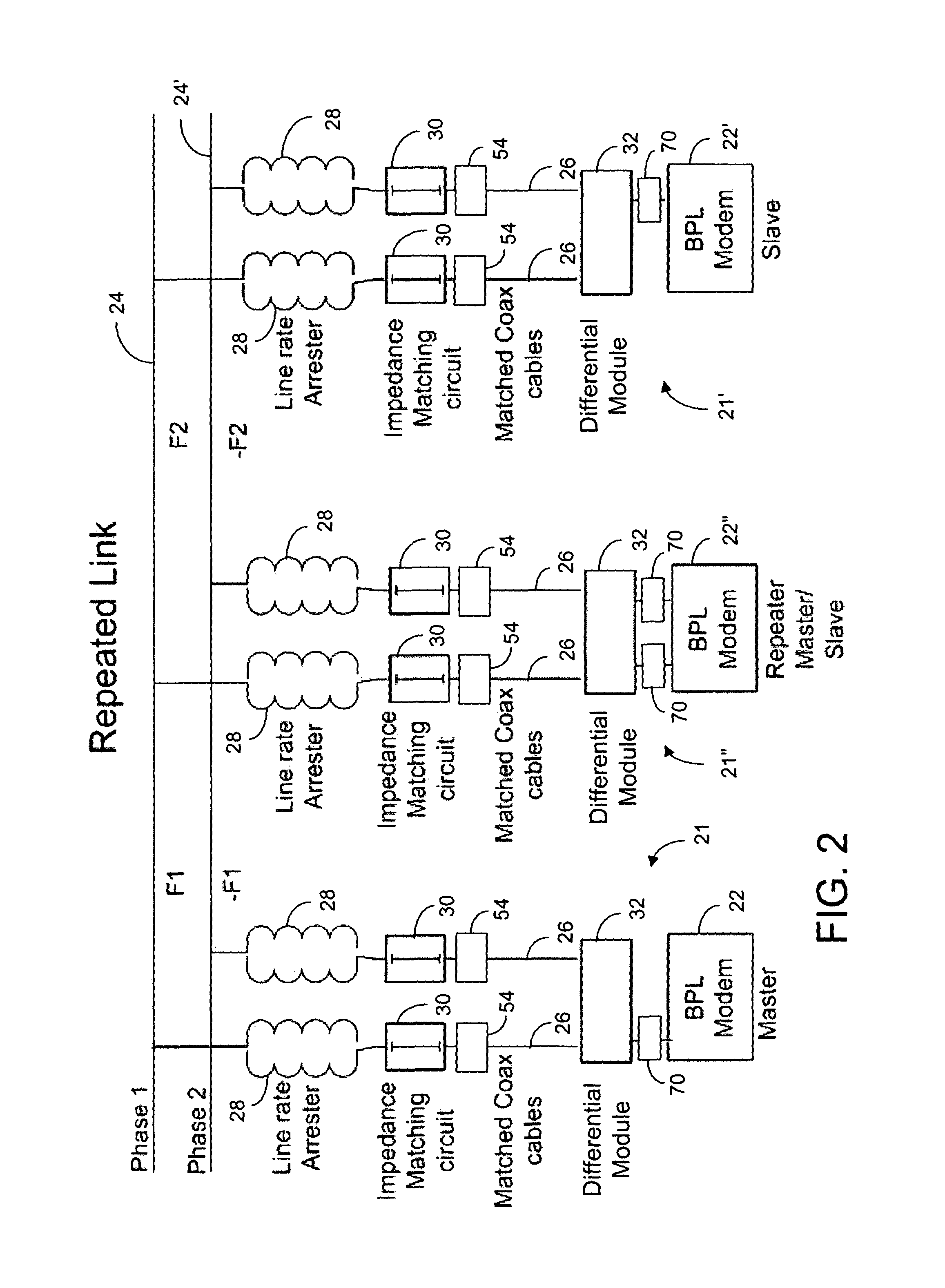
[0090]A second embodiment of the present invention is the first embodiment operating in FDM (Frequency Division Multiplexing) and / or TDM (Time Division Multiplexing) mode. In FDM mode, BPL modems are configured as master or slave. In TDM mode, BPL modems are configured as TDM repeater.

[0091]A third embodiment of the present invention is the second embodiment, over a single or multiple line segments. When multi...


PUM


Abstract

A communication device for use on high voltage power lines provides for broadband communications over such high voltage power lines. The device has an impedance matching circuit configured to connect at one end to a high voltage line arrester of the high voltage power line, as well as a limiter circuit coupled to the other end of the impedance matching circuit to limit a voltage associated with a broadband signal. A noise blanker circuit is coupled at one end to this other end of the impedance matching circuit and is configured to inhibit presentation of a time delayed incoming signal to the broadband modem upon detection of electrical noise. The communication device can further comprise link aggregation and / or a differential circuit for providing non-inverted and inverted broadband signals for both reception and transmission. A corresponding method of communicating broadband information over a high voltage power line is disclosed.

Description

CROSS REFERENCE TO RELATED APPLICATION[0001]This application claims priority under 35 USC §119 to U.S. Provisional Patent Application No. 61 / 158,312 filed on Mar. 6, 2009.TECHNICAL FIELD[0002]The present invention relates to communications between electrical utility substations using Broadband over Powerline also known as BPL technology over High Voltage (HV defined as 138 KV and above) transmission lines and Medium Voltage (MV) sub-transmission and distribution lines.BACKGROUND OF THE INVENTION[0003]BPL has been used over Low Voltage (LV) lines for in home networking applications and over Medium Voltage (MV) distribution lines for last mile access of broadband and smart grid applications. This is the first adaptation of this technology for station to station communications over electrical transmission lines. The characteristics of electrical transmission lines are a good match for BPL since the line loss (measured in, for example, dB per linear feet) is much lower than MV distribut...

Claims


Application Information

Patent Timeline
Patent Type & Authority Patents(United States)
IPC IPC(8): H04L5/14H04M1/00H04M11/00
CPCH04B3/56H04B2203/5483H04B2203/5425
Inventor SADAN, NACHUMSTRANDBERG, NORMAN A.TRIOLI, PHILIP M.RENZ, BRUCE A.
Owner GRIDEDGE NETWORKS
Learn More