Heat dissipating structure and battery provided with the same

Active Publication Date: 2020-08-13
SHIN-ETSU POLYMER CO LTD
View PDF0 Cites 1 Cited by
  • Summary
  • Abstract
  • Description
  • Claims
  • Application Information

AI Technical Summary

Benefits of technology

[0009]The present invention provides a heat dissipating structure adaptable to various forms of heat source, light in weight, elastically deformable, excellent in heat di

Problems solved by technology

A control system of automobiles, aircrafts, ships or electronic devices for home use or business use has become further complicated and highly accurate, and correspondingly the integration of small electronic components on a circuit board has been increasingly densified.
Above all, the method of forming the circuit board itself using the material excellent in heat dissipation, for example, diamond, aluminum nitride (AlN), cubic boron nitride (cBN) or the like extremely increases the cost of the circuit board.
Additionally, placement of the cooling fan causes problems of malfunction of a fan as the rotator, need of maintenance for preventing the malfunction, and difficulty in securing a mount spa

Method used


Image

  • Heat dissipating structure and battery provided with the same
  • Heat dissipating structure and battery provided with the same
  • Heat dissipating structure and battery provided with the same

Examples


Example

First Embodiment

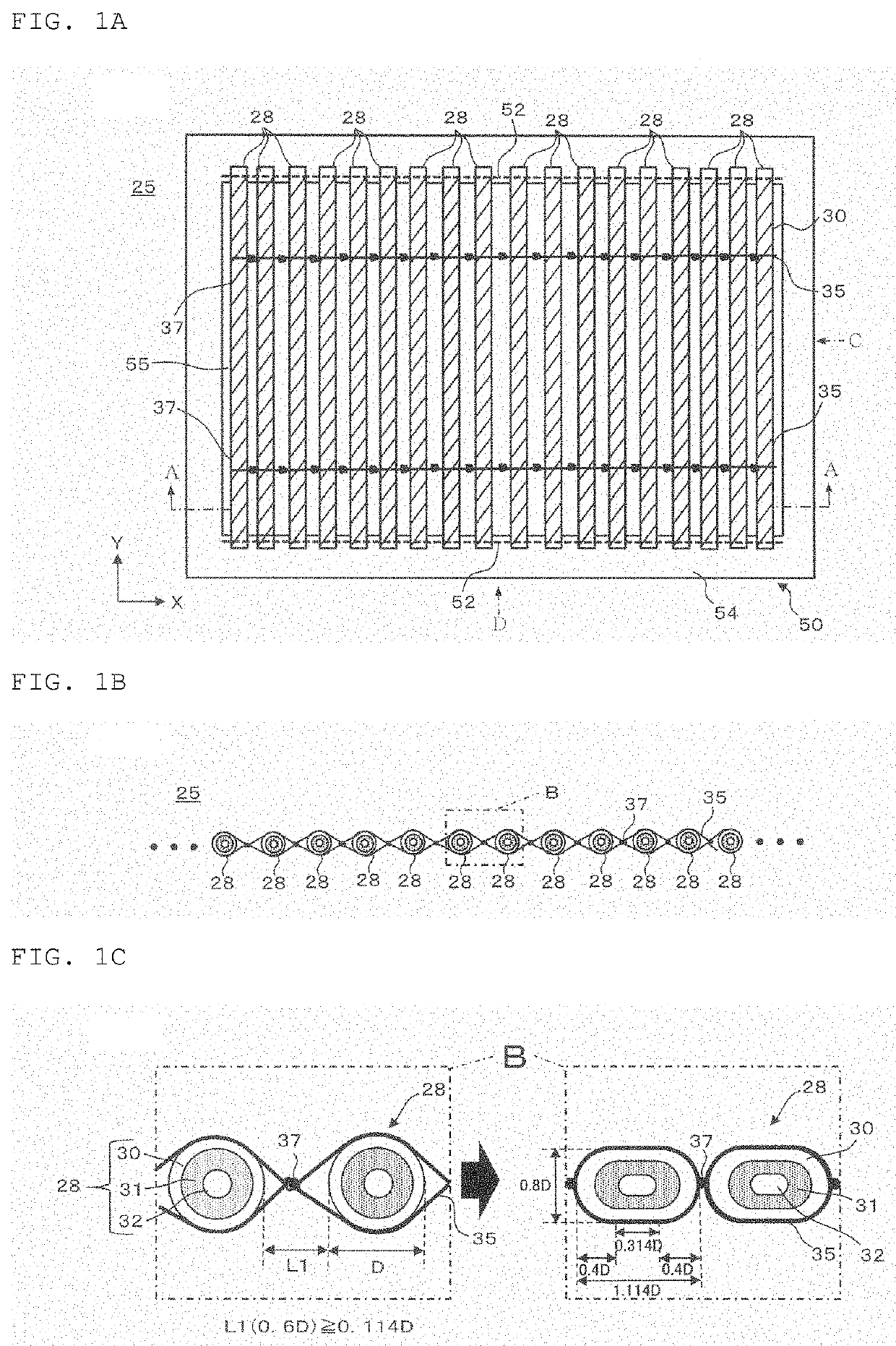
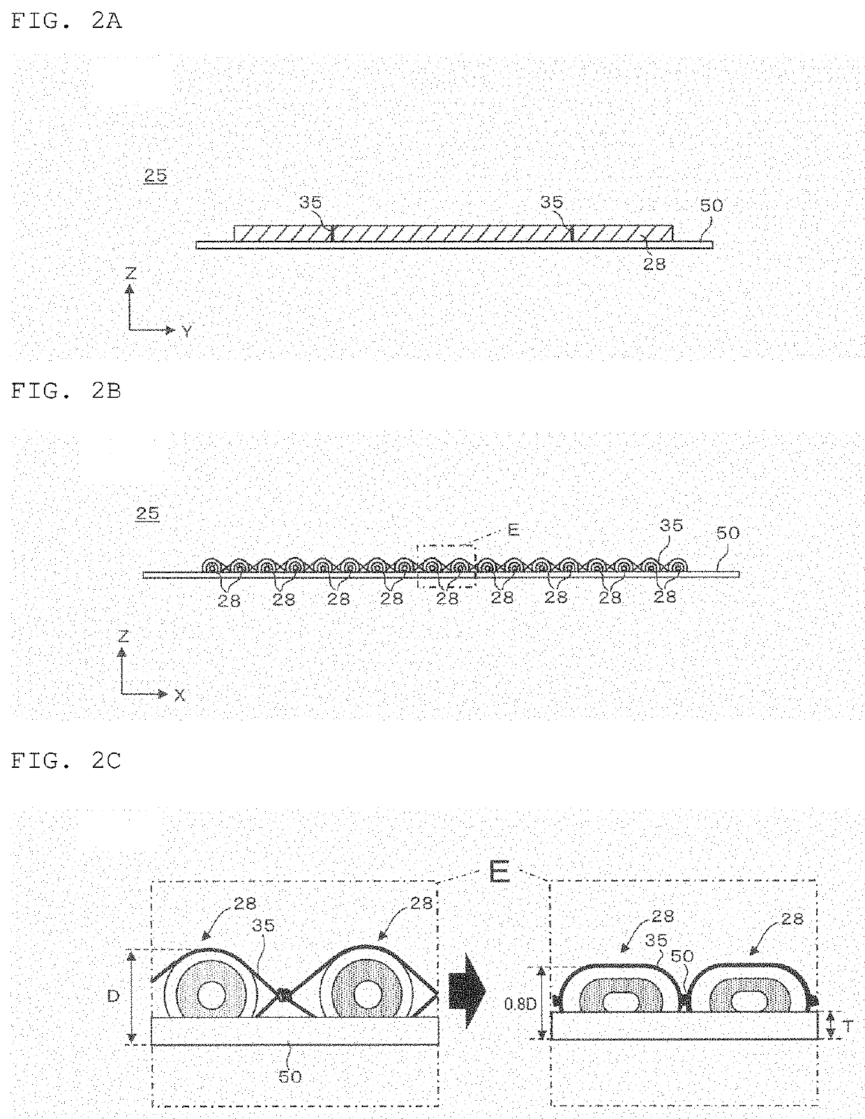
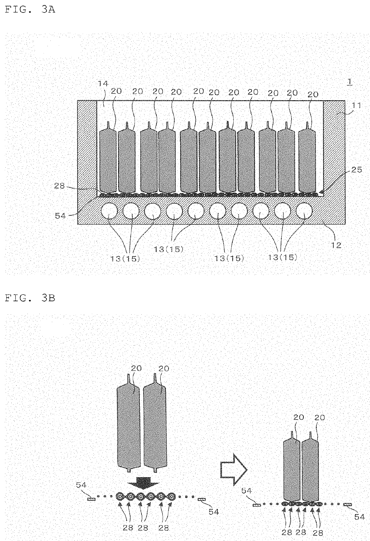
[0031]FIG. 1A is a plan view of a heat dissipating structure according to a first embodiment. FIG. 1B is a longitudinal sectional view taken along line A-A of FIG. 1A. FIG. 1C is an enlarged view of a region B as shown in FIG. 1B. FIG. 2A is a side view of the heat dissipating structure of FIG. 1A viewed from an arrow C direction. FIG. 2B is a side view of the heat dissipating structure of FIG. 1A viewed from an arrow D direction. FIG. 2C is an enlarged view of a region E of FIG. 2B. FIG. 3A is a longitudinal sectional view of the heat dissipating structure according to the first embodiment, and a battery provided with the heat dissipating structure. FIG. 3B is a sectional view illustrating change in the formation of the heat dissipating structure before and after it is compressed by battery cells as shown in FIG. 3A.

[0032]As illustrated in FIG. 3A and FIG. 3B, a battery 1 is structured to have a plurality of battery cells 20 in a housing 11 in contact with cooling ...

Example

Second Embodiment

[0059]A heat dissipating structure according to a second embodiment, and a battery provided with the heat dissipating structure are described. Portions common with those of the first embodiment are denoted by the same reference numerals, and redundant description is omitted.

[0060]FIG. 5A is a plan view of the heat dissipating structure according to the second embodiment. FIG. 5B is a sectional view taken along line F-F of FIG. 5A. FIG. 5C is an enlarged view of a region G of FIG. 5B.

[0061]Unlike the heat dissipating structure 25 of the first embodiment, a heat dissipating structure 25a of the second embodiment has the plurality of heat dissipating members 28 connected by connection members 35a. Other configuration except the connection member 35a is common with that of the first embodiment, and an explanation thereof, thus is omitted.

[0062]Likewise the connection member of the first embodiment, the connection member 35a is formed of the thread or the rubber as the ...

Example

Third Embodiment

[0064]A heat dissipating structure according to a third embodiment and a battery provided with the heat dissipating structure are described. Portions common with those of the embodiments are denoted by the same reference numerals, and redundant description is omitted.

[0065]FIG. 6 is a longitudinal sectional view of the heat dissipating structure according to the third embodiment, and a battery provided with the heat dissipating structure. FIG. 7A shows a part of a process of forming the heat dissipating structure of the third embodiment. FIG. 7B is a plan view of the heat dissipating structure formed by the process as shown in FIG. 7A.

[0066]A battery 1a according to the third embodiment includes a heat dissipating structure 25b different from the heat dissipating structure 25 disposed in the battery 1 according to the first embodiment, and has the other structure common with the battery 1. The heat dissipating structure 25b used in this embodiment is formed by connec...


PUM


Abstract

A heat dissipating structure for a battery includes a plurality of heat dissipating members connected for enhancing heat dissipation from a heat source and a fixation member. The heat dissipating member includes a spirally winding shaped heat conduction sheet for conducting heat from the heat source, a cushion member that is provided on an annular back surface of the heat conduction sheet, and deformable following a surface shape of the heat source more easily than the heat conduction sheet, and a through passage penetrating in a winding direction of the heat conduction sheet. The fixation member fixes the heat dissipating members orthogonally arranged to a longitudinal direction thereof. The fixation member fixes at least each one end of the heat dissipating members in the longitudinal direction.

Description

CROSS REFERENCE[0001]The present application claims the benefit of priorities of Japanese Patent Application No. 2019-020327 filed on Feb. 7, 2019 the entire contents of which are incorporated herein by reference. The entire contents of patents, patent applications, and literatures cited in the present application are also incorporated herein by reference.TECHNICAL FIELD[0002]The present invention relates to a heat dissipating structure and a battery provided with the same.RELATED ART[0003]A control system of automobiles, aircrafts, ships or electronic devices for home use or business use has become further complicated and highly accurate, and correspondingly the integration of small electronic components on a circuit board has been increasingly densified. As a result, it is strongly requested to solve malfunction or shortening of service life of the electronic components owing to heat generated in the periphery of the circuit board.[0004]Conventionally, rapid heat dissipation from ...

Claims


Application Information

Patent Timeline
IPC IPC(8): H01M10/613H05K7/20H01M10/6551H01M10/6556H01M10/653H01M50/204
CPCH01M10/653H01M10/6556H05K7/20263H01M10/6551H01M10/613H01M10/617H01M10/625H01M10/6568H01M10/6554H01M50/204F28F21/02H01M10/647F28F2013/006F28D2021/0029F28D1/02Y02P70/50H01M10/655
Inventor SHIMIZU, TAKAOANDERSSON, NILSCHRIST, MARKUSBROMMER, CHRISTIANSCHNUEPKE, HUBERTFUCHSLOCHER, MARC
Owner SHIN-ETSU POLYMER CO LTD
Why Eureka
Try Eureka