Heat sink with heat dissipating fins and method of manufacturing heat sink

Inactive Publication Date: 2009-11-03
FURUKAWA ELECTRIC CO LTD
View PDF3 Cites 9 Cited by
  • Summary
  • Abstract
  • Description
  • Claims
  • Application Information

AI Technical Summary

Benefits of technology

[0012]An object of the invention is to provide a heat sink with heat dissipating fins and the method therefore in which the manufacturing cost is low, the heat dissipating efficiency is excellent without lowering the shield effect, and it may be used in the thin-type electronic device.
[0013]The inventors have intensively studied to overcome the above-mentioned problem. As a result, it has been found that when the same number of the slits as the number of the heat dissipating fins are formed in the metal shield plate member and the heat dissipating fins are inserted into the respective slits of the metal shield plate member, the shield effect can be prevented from being lowered. Furthermore, it has been found that when the L shaped heat dissipating fin comprising a heat receiving portion and a heat dissipating portion is employed such that the heat receiving portion directly contacts with the heat generating device, the metal block is not necessary anymore, thus enabling to use in the thin type electronic device. Furthermore, it has been found that when the part of the heat dissipating fin is inserted into the part of the slit using the elasticity of the flat plate type heat dissipating fin and then the remaining part of the heat dissipating fin is pushed down into the slit along the shape of the slit, the heat dissipating fin is easily inserted and fixed into the slit.

Problems solved by technology

However, since the space between the circuit board and the inner surface of the box is narrow in a thin-type electronic device, the space between the metal shield plate member and the circuit board becomes narrow, accordingly.
By means of the heat dissipating method in which the heat generated by the heat generating device is received by the heat transfer block or the like, and dissipated to a specific place or air through the heat dissipating fin, there is a problem that the metal block or the like may not be provided within the thin-type electronic device.
Furthermore, when the space between the metal shield plate member and the circuit board is narrow and a consuming power of the heat generating device is large, the corresponding portion of the metal shield plate member to the heat dissipating fins of the heat sink is cut off, thus lowering the shield effect.
Furthermore, since the metal plate, block or the like is positioned in the heat path between the heat source and the heat dissipating fin and the contact heat resistance is produced between the metal plate, block or the like, the heat dissipating efficiency of the whole heat sink comes to deteriorate.

Method used


Image

  • Heat sink with heat dissipating fins and method of manufacturing heat sink
  • Heat sink with heat dissipating fins and method of manufacturing heat sink
  • Heat sink with heat dissipating fins and method of manufacturing heat sink

Examples


Embodiment Construction

[0055]Referring now to the drawings, the embodiments of the heat sink with fins of the invention and the method of manufacturing same will be explained in detail.

[0056]The first embodiment of the method of manufacturing a heat sink of the invention comprises the steps of:

[0057]preparing a metal plate having a plurality of slits and a plurality of metal fins each having a heat receiving portion and a heat dissipating portion;

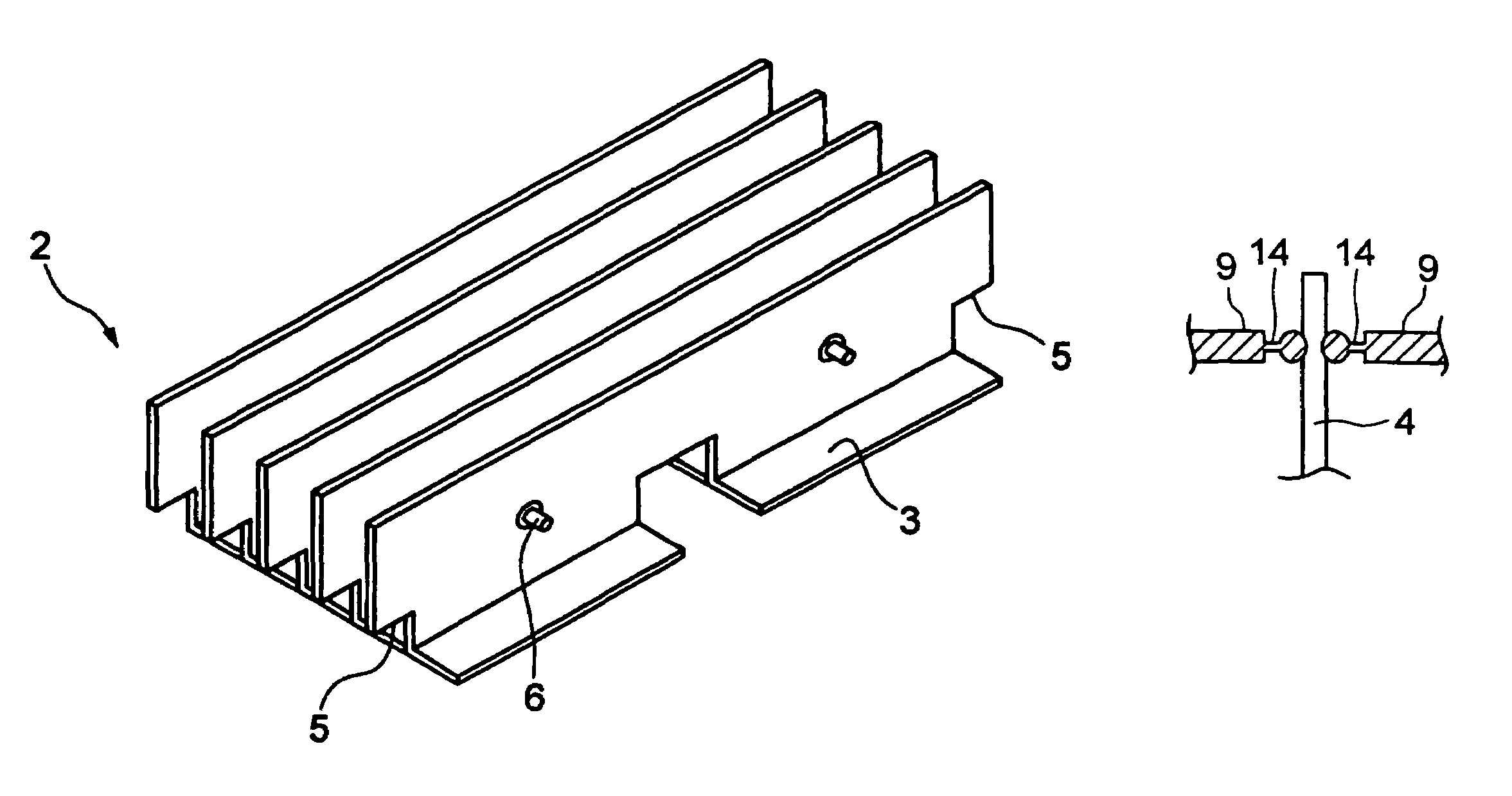
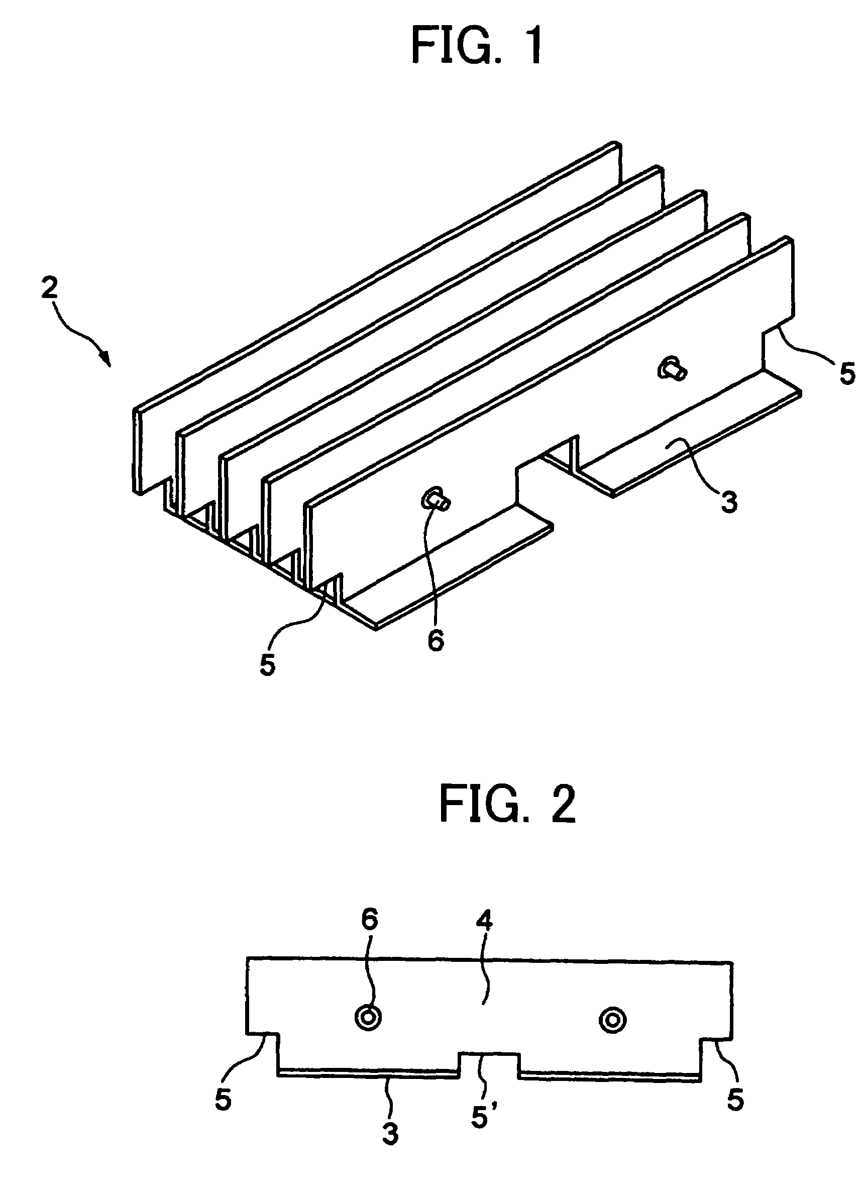
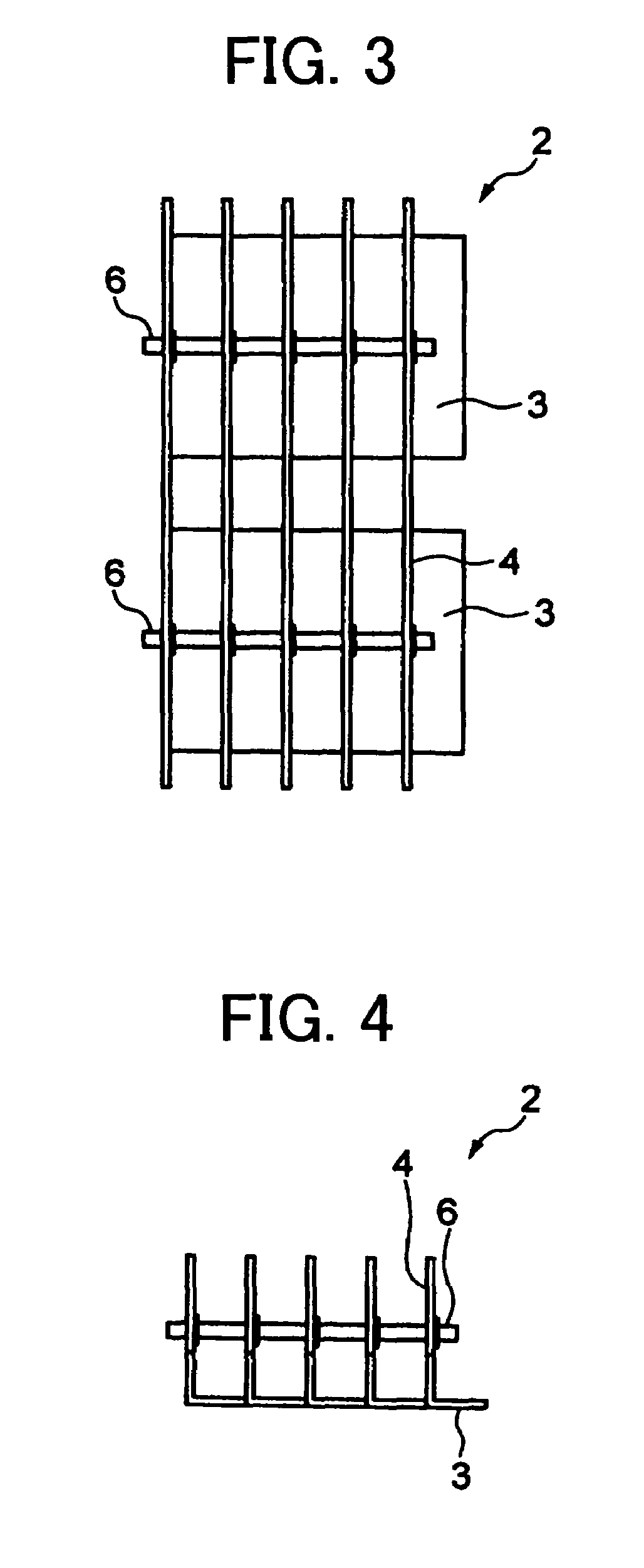
[0058]inserting respective parts of said heat dissipating portions of said metal fins into respective slits of said metal plate;

[0059]pushing respective remaining parts of said heat dissipating portions down to a specific depth along said slits having a prescribed shape in such manner that said fins are press-connected to said metal plate.

[0060]FIG. 5 is a schematic view showing a metal shield plate member having a plurality of slits of a prescribed shape. As shown in FIG. 5, the metal plate member 7 comprises a metal shield plate member for an electromagnetic sh...


PUM

PropertyMeasurementUnit
Elasticityaaaaaaaaaa

Abstract

A heat sink comprising: a heat dissipating portion comprising a plurality of metal fins each having a heat receiving portion and a heat dissipating portion having elasticity; a fin fixing member to transfix said plurality of metal fins; a metal plate having a plurality of slits into which said respective heat dissipating portions are inserted and press-connected thereto with use of said elasticity; and a joining portion to join said metal plate and said heat dissipating portions which are inserted into said respective slits and fixed thereto.

Description

BACKGROUND OF THE INVENTION[0001]1. Field of the invention[0002]The present invention relates to a heat sink and a method of manufacturing the heat sink. The heat sink with the heat dissipating fins of the invention is applicable to a heat sink for heat dissipating and cooling of the heat generating electronic components such as electronic devices as represented by personal computers, game devices, for example, and in addition to the heat dissipation and cooling in all the field necessary to be heat-dissipated.[0003]2. Related Art[0004]Semiconductor chips and the like used in various electronics devices such as personal computer, game device, audio device or the like are downsized and densely integrated so that the processing speed is remarkably improved to result in higher heat-generating density.[0005]As a means for dissipating the heat generated by electronic devices such as personal computer, game device, audio device or the like including semiconductor chips with high heat-gene...

Claims


Application Information

Patent Timeline
IPC IPC(8): H05K7/20B21D53/02H01B7/42H01L23/34F28D15/02H01L21/48H01L23/36H01L23/40H01L23/427H01L23/467
CPCF28F3/02H01L21/4882H01L23/467F28D15/0266Y10T29/4935H01L2924/0002H01L2924/00H05K7/2039H05K9/0026
Inventor SASAKI, CHIYOSHI
Owner FURUKAWA ELECTRIC CO LTD
Why Eureka
Try Eureka