Power supply protection circuit

Active Publication Date: 2020-08-13
NUVOTON TECH CORP JAPAN
View PDF0 Cites 0 Cited by
  • Summary
  • Abstract
  • Description
  • Claims
  • Application Information

AI Technical Summary

Benefits of technology

The power supply protection circuit in the patent allows for the selection of a wide variety of protection switches, making it easier to design. This means that more options are available for protecting power supplies, which can save time and increase efficiency.

Problems solved by technology

In general, if a PNP transistor (or Pch MOSFET) and a NPN transistor (or Nch MOSFET) have the same shape, the NPN transistor (or Nch MOSFET) can have a lower conduction voltage when turned on, but it is problematic in that a voltage higher than the power supply voltage is required as the driving voltage, which requires a complex driving circuit.

Method used


Image

  • Power supply protection circuit
  • Power supply protection circuit
  • Power supply protection circuit

Examples


embodiment 1

[0056]A power supply protection circuit according to Embodiment 1 will be described with reference to the drawings.

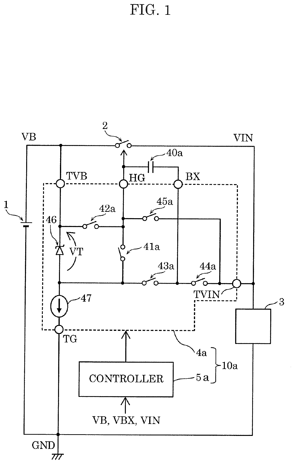
[0057]FIG. 1 is an overall circuit diagram of the power supply protection circuit according to Embodiment 1.

[0058]As shown in FIG. 1, power supply protection circuit 10a is a circuit that controls protection switch 2 provided on a power supply line connecting direct current power supply 1 and load circuit 3. Power supply protection circuit 10a includes circuitry 4a that is connected to protection switch 2 and controller 5a that switches the operation state of circuitry 4a between a first state and a second state.

[0059]The first state of circuitry 4a is an operation state in which driving of protection switch 2 is enabled in the case where protection switch 2 is a first semiconductor switch having a control terminal connected to a semiconductor layer of a first conductivity type. The second state of circuitry 4a is an operation state in which driving of protection switch...

embodiment 2

[0096]A power supply protection circuit according to Embodiment 2 will be described. The power supply protection circuit according to Embodiment 2 is different from power supply protection circuit 10a according to Embodiment 1 mainly in terms of the configurations of the first driving circuit and the second driving circuit. Hereinafter, the power supply protection circuit according to Embodiment 2 will be described with reference to the drawings, focusing on the differences from power supply protection circuit 10a according to Embodiment 1.

[0097]FIG. 8 is an overall circuit diagram of power supply protection circuit 10b according to Embodiment 2.

[0098]As shown in FIG. 8, power supply protection circuit 10b according to Embodiment 2 includes circuitry 4b and controller 5b.

[0099]Circuitry 4b includes: power supply terminal TVB that is connected to direct current power supply 1; driving terminal HG that is connected to the control terminal of protection switch 2; first terminal BX; co...

embodiment 3

[0124]A power supply protection circuit according to Embodiment 3 will be described. The power supply protection circuit according to Embodiment 3 is different from the power supply protection circuits according to Embodiments 1 and 2 mainly in terms of the configurations of the first driving circuit and the second driving circuit. Hereinafter, the power supply protection circuit according to Embodiment 3 will be described with reference to the drawings, focusing on the differences from the power supply protection circuits according to Embodiments 1 and 2 described above.

[0125]FIG. 15 is an overall circuit diagram of power supply protection circuit 10c according to Embodiment 3.

[0126]As shown in FIG. 15, power supply protection circuit 10c according to Embodiment 3 includes circuitry 4c and controller 5c.

[0127]Circuitry 4c includes: power supply terminal TVB that is connected to direct current power supply 1; driving terminal HG that is connected to the control terminal of protecti...


PUM


Abstract

A power supply protection circuit is a circuit that controls a protection switch provided on a power supply line connecting a direct current power supply and a load circuit. The power supply protection circuit includes: circuitry connected to the protection switch; and a controller that switches an operation state of the circuitry between a first state and a second state. The first state is an operation state in which driving of the protection switch is enabled when the protection switch is a first semiconductor switch having a control terminal connected to a semiconductor layer of a first conductivity type. The second state is an operation state in which driving of the protection switch is enabled when the protection switch is a second semiconductor switch having a control terminal connected to a semiconductor layer of a second conductivity type that is different from the semiconductor layer of a first conductivity type.

Description

CROSS REFERENCE TO RELATED APPLICATIONS[0001]This application is a U.S. continuation application of PCT International Patent Application Number PCT / JP2018 / 039931 filed on Oct. 26, 2018, claiming the benefit of priority of Japanese Patent Application Number 2017-209739 filed on Oct. 30, 2017, the entire contents of which are hereby incorporated by reference.BACKGROUND1. Technical Field[0002]The present disclosure relates to a power supply protection circuit.2. Description of the Related Art[0003]A power supply protection circuit according to a conventional technique is known in which a protection switch is provided between a direct current power supply and a load circuit, and the protection switch is shut down when an anomaly in the load circuit is detected. Such a power supply protection circuit will be described with reference to FIGS. 30 and 31.[0004]FIG. 30 is a circuit diagram showing a schematic configuration of a power supply protection circuit according to a conventional tech...

Claims


Application Information

Patent Timeline
IPC IPC(8): H02M1/32H02H7/20
CPCH02M1/32H02H7/20H02H3/087H02H3/40H02H3/20H02H9/02H02H3/08G05F1/10H02H1/00
Inventor ISHII, TAKUYAMIHASHI, TETSUYAKATASE, GINGARYU, TAKASHI
Owner NUVOTON TECH CORP JAPAN
Why Eureka
Try Eureka