Grinding apparatus

a technology of grinding machine and grinding chamber, which is applied in the direction of grinding feeder, grinding machine components, manufacturing tools, etc., can solve the problems of increasing the operation time for grinding and bottlenecking in reducing so as to reduce the operation time required for grinding and improve the productivity. , the effect of increasing the grinding operation tim

Inactive Publication Date: 2020-08-20
DISCO CORP
View PDF5 Cites 2 Cited by
  • Summary
  • Abstract
  • Description
  • Claims
  • Application Information

AI Technical Summary

Benefits of technology

[0005]In the past, the cleaning unit has been provided with an elevating mechanism for vertically moving the cleaning unit in a large amount, so as to avoid the possibility that the cleaning unit may collide with the loading means for loading the wafer to the chuck table before grinding or the unloading means for unloading the wafer from the chuck table after grinding. However, when the two-fluid cleaning portion and the abrasive cleaning portion of the cleaning unit are being vertically moved by operating the elevating mechanism, the loading means and the unloading means must wait, causing a bottleneck in reducing the operation time required for grinding. That is, there is a problem such that the operation time for grinding is increased by the vertical movement of the cleaning unit. Further, when the loading means and the unloading means are waiting, it is desired that the wafer to be ground can be set on the temporary setting table and that the wafer ground can be cleaned by the spinner, thereby improving the productivity.

Problems solved by technology

However, when the two-fluid cleaning portion and the abrasive cleaning portion of the cleaning unit are being vertically moved by operating the elevating mechanism, the loading means and the unloading means must wait, causing a bottleneck in reducing the operation time required for grinding.
That is, there is a problem such that the operation time for grinding is increased by the vertical movement of the cleaning unit.

Method used


Image

  • Grinding apparatus
  • Grinding apparatus
  • Grinding apparatus

Examples


Embodiment Construction

[0030]1. Configuration of Grinding Apparatus

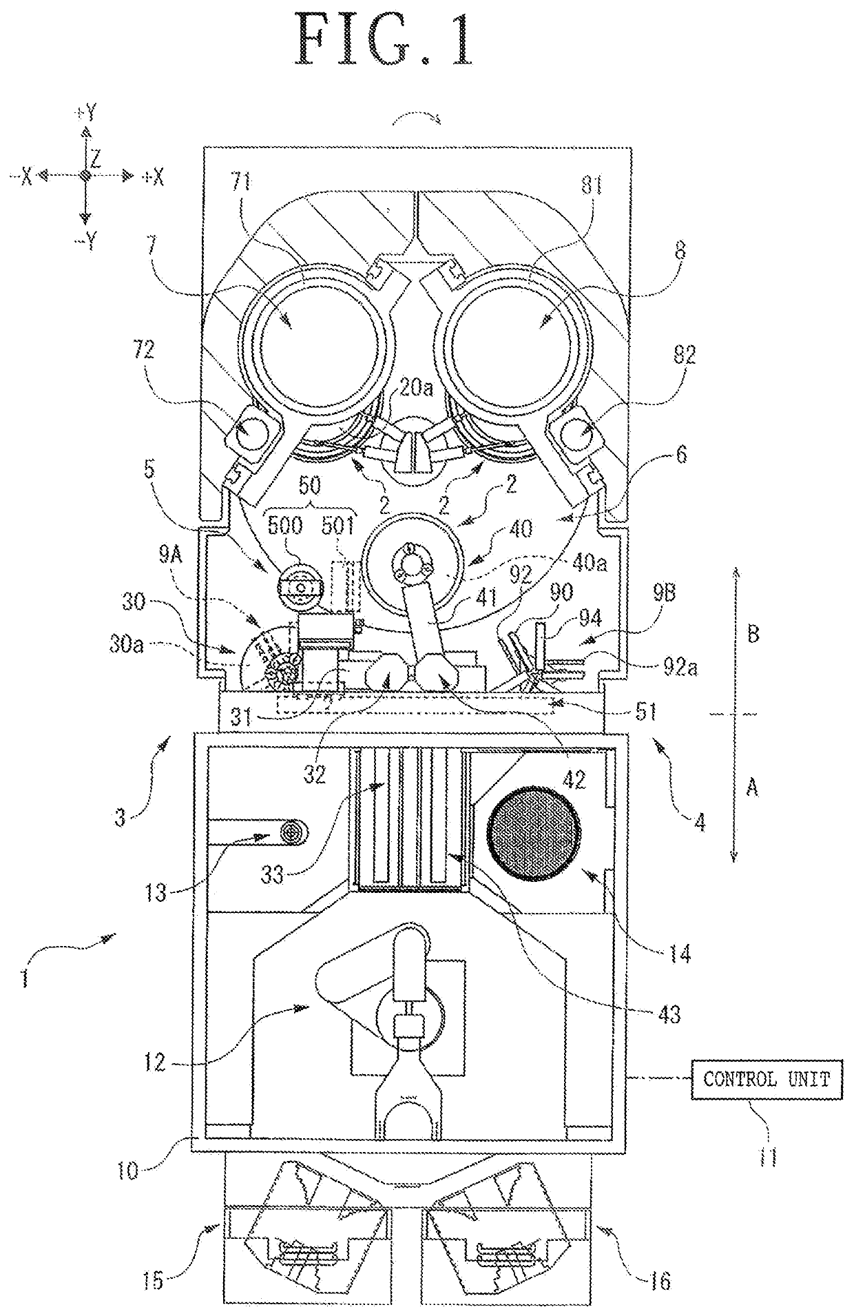
[0031]Referring to FIG. 1, there is depicted a grinding apparatus 1 in plan. The grinding apparatus 1 is an apparatus for grinding a wafer W as a plate-shaped semiconductor workpiece by using a first grinding unit 7 and a second grinding unit 8. The wafer W has an upper surface Wa and a lower surface Wb. The configuration of the grinding apparatus 1 will now be described. In the following description, the X direction includes the +X direction depicted by an arrow +X in the drawings and the −X direction depicted by an arrow −X in the drawings. Similarly, the Y direction includes the +Y direction depicted by an arrow −Y in the drawings and the −Y direction depicted by an arrow −Y in the drawings. Further, the Z direction includes the +Z direction depicted by an arrow in the drawings and the −Z direction depicted by an arrow −Z in the drawings. The X direction and the Y direction are perpendicular to each other to define a horizontal plane, a...


PUM


Abstract

A grinding apparatus includes a loading unit for loading a wafer to a chuck table having a holding surface for holding the wafer, an unloading unit for unloading the wafer from the chuck table, and a cleaning unit for cleaning the holding surface of the chuck table or the upper surface of the wafer held on the holding surface of the chuck table. The cleaning unit includes a cleaning portion and a horizontal moving portion for horizontally moving the cleaning portion in a lateral direction of the grinding apparatus. The loading unit has a first holding portion for holding the wafer, and the unloading unit has a second holding portion for holding the wafer.

Description

BACKGROUND OF THE INVENTIONField of the Invention[0001]The present invention relates to a grinding apparatus.Description of the Related Art[0002]In the operation of a grinding apparatus, a robot is first operated to draw a wafer out of a cassette storing a plurality of wafers supported on shelves. Thereafter, the wafer is transferred to a temporary setting table by the robot and then positioned on the temporary setting table. Thereafter, loading means having a swing arm and a loading pad is operated to load the wafer from the temporary setting table to a chuck table having a holding surface for holding the wafer. Thereafter, the wafer held on the chuck table is ground by using a grinding wheel having abrasive members. Thereafter, a cleaning unit is operated to spray a two-component fluid composed of air and water toward the upper surface (work surface) of the wafer ground by the abrasive members of the grinding wheel, thereby cleaning the upper surface of the wafer. Thereafter, unlo...

Claims


Application Information

Patent Timeline
Patent Type & Authority Applications(United States)
IPC IPC(8): B24B55/06B24B7/04H01L21/304H01L21/683B24B7/22B24B41/00B24B41/06
CPCH01L21/683H01L21/304B24B41/06B24B7/04B24B41/005B24B55/06B24B7/228H01L21/67046H01L21/67219
Inventor YOSHII, SHUNGOMATSUBARA, SOUICHIFUKUSHI, NOBUYUKINAKAYAMA, HIDEKAZU
Owner DISCO CORP
Why Eureka
Try Eureka