Unit for detecting the filling level of a liquid in a container, braking system, and method

a technology for liquid detection and container, applied in braking systems, braking components, transportation and packaging, etc., can solve the problems of increased wiring complexity, malfunction must be present, and the detected filling level cannot be trusted, so as to ensure the functional capability of the switching uni

Active Publication Date: 2020-08-20
ROBERT BOSCH GMBH
View PDF0 Cites 0 Cited by
  • Summary
  • Abstract
  • Description
  • Claims
  • Application Information

AI Technical Summary

Benefits of technology

[0006]According to one preferred specific embodiment of the present invention, it is provided that the coil is designed to be coaxial with respect to the switching unit. Therefore, the coil encompasses the switching unit and generates, also in the case of low current or low voltage, a sufficient magnetic field, which suffices for actuating the switching unit. As a result, a compact and efficient design of the unit is provided. If the magnetic device is designed as an electromagnet or includes an electromagnet, the electromagnet is preferably situated next to the switching unit or at the switching unit, although only on one side thereof, in order to generate a targeted magnetic field for actuating the switching unit.
[0008]Moreover, it is preferably provided that the coil includes a first and a second electrical coil terminal, and that the switching unit includes a first and a second electrical switch terminal, the terminals each being directly connected to the testing unit. The direct connection is understood to mean such a connection in which no further elements, apart from electrical lines, are interconnected and no interconnections of the terminals among one another takes place. Due to the testing unit, therefore, the coil is activatable independently of the switching unit, so that an advantageous evaluation of the test result may take place. It may be disadvantageous in this case that four terminals of the unit are situated within the container and must be routed toward the outside, which results in an increased wiring complexity as compared to conventional units that include a reed contact. Since, in addition, the elements within the container must be protected against the carried-along liquid, an appropriately increased sealing outlay is necessary for sealing off the electrical connections.
[0009]Alternatively, it is preferably provided that the first coil terminal is directly connected to the first switch terminal and the second coil terminal is directly connected to the second switch terminal. As a result, the coil is directly electrically connected to the switching unit and does not need a separate terminal for the connection to the testing unit. Due to the interconnection of the coil and the switching unit to one another, a simple approach for operating the unit has been found, in the case of which, via the application of a voltage to the switching unit, a current is simultaneously generated through the coil, which generates the magnetic field for actuating the switching unit. Provided the generated magnetic field is not yet sufficient for actuating the switching unit, the current flowing through the unit of the switching unit of the coil corresponds to the connected voltage and the electrical resistance of the coil and, therefore, may be easily evaluated. As soon as the switching state of the switching unit changes due to the increasing magnetic field, this is easily detectable by the unit due to a change of the current flow. As a result, it may be easily differentiated whether the switching unit has switched or not. If a switching process fails to appear, because a malfunction is present in the switching unit, the detected actual current behaves differently, because the short-circuiting of the electrical connection with the aid of the switching unit and / or the interruption of this electrical connection do / does not take place.
[0010]As described, the switching unit and the coil preferably form a unit, in particular a mechanical unit, which is manageable as a component or an assembly, and, in particular, includes only two electrically contactable terminals. As a result, a simple electrical contacting is possible in combination with low wiring complexity and sealing outlay, which corresponds to the outlay associated with a conventional unit. Nevertheless, the aforementioned advantages are provided, so that the aforementioned testing function is implementable despite this simple contactability.

Problems solved by technology

If the expected response fails to appear, however, it is established that a malfunction must be present at the switching unit and, therefore, the detected filling level is not permitted to be trusted.
It may be disadvantageous in this case that four terminals of the unit are situated within the container and must be routed toward the outside, which results in an increased wiring complexity as compared to conventional units that include a reed contact.

Method used


Image

  • Unit for detecting the filling level of a liquid in a container, braking system, and method
  • Unit for detecting the filling level of a liquid in a container, braking system, and method

Examples


Embodiment Construction

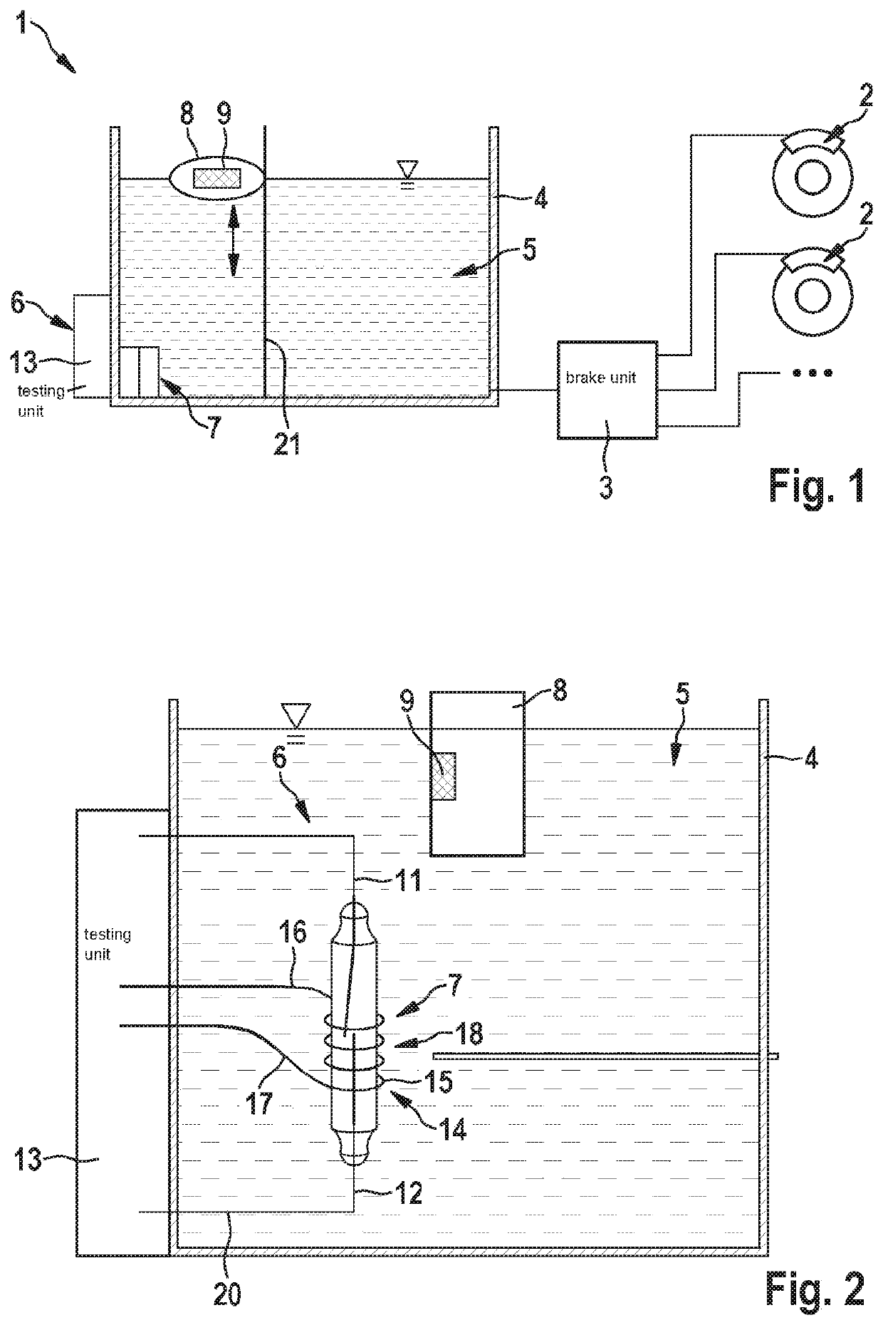
[0020]FIG. 1 shows, in a simplified representation, parts of a braking system 1 for a motor vehicle, which includes multiple hydraulically actuatable wheel brakes 2, which are hydraulically actuated by a brake unit 3, for example, an ABS or ESP unit. For this purpose, braking system 1 includes a hydraulic circuit, which, inter alia, also includes a container 4 for liquid 5 utilized in braking system 1.

[0021]In order to monitor the filling level of the liquid located in container 4, brake fluid in this case, and, in particular, to detect whether the filling level falls below a critical value, a unit 6 is assigned to container 4, which includes a magnetically actuatable switching unit 7 fixedly situated at container 4. In addition, a float gauge 8 of unit 6, which carries a permanent magnet 9, is situated in container 4. Float gauge 8 always lies on the surface of liquid 5, so that its level in container 4 corresponds to the liquid level and the filling level of liquid 5 in container ...


PUM


Abstract

A unit for detecting a filling level of a liquid in a container. The unit includes at least one float gauge, which carries at least one permanent magnet, and including at least one switching unit, which is actuatable by the permanent magnet and is fastened in or at the container. It is provided that at least one energizable magnetic device for generating a magnetic field is assigned to the switching unit, which, when sufficiently energized, generates a magnetic field, which actuates the switching unit when the switching unit is functional.

Description

FIELD[0001]The present invention relates to a unit for detecting a filling level of a liquid in a container, including at least one float gauge, which carries at least one permanent magnet, and including at least one switching unit, which is actuatable by the permanent magnet and is fastened in or at the container.[0002]Moreover, the present invention relates to a braking system including such a unit and to a method for operating the unit or the braking system.BACKGROUND INFORMATION[0003]In order to determine the filling level of liquids, which are carried along in the motor vehicle as operating means, such as brake fluid or cooling water, or the like, conventional units are provided, which automatically monitor the filling level of the liquid in the container storing them. In the process, it is not absolutely necessary to detect the specific filling level, but rather to detect whether the filling level falls below a critical value. In order to detect this, conventional units includ...

Claims


Application Information

Patent Timeline
Patent Type & Authority Applications(United States)
IPC IPC(8): G01F23/74B60T11/26B60Q9/00B60T17/06B60T17/22
CPCB60Q9/00B60T17/225B60T17/06G01F23/74B60T11/26
Inventor KUNZ, MICHAEL
Owner ROBERT BOSCH GMBH
Why Eureka
Try Eureka