
Vibration decoupler

a technology of vibration decoupler and damper, which is applied in the direction of spring/damper design characteristics, couplings, mechanical equipment, etc., can solve the problems of occupying a relatively large installed space in the engine, requiring a relatively large number of component parts, and limited reduction of torsional vibration, so as to reduce torsional vibration and occupy a small space. , the effect of simple construction

Inactive Publication Date: 2004-04-29
BOMBARDIER ROTAX
View PDF5 Cites 0 Cited by
  • Summary
  • Abstract
  • Description
  • Claims
  • Application Information

AI Technical Summary

Benefits of technology

[0016] For this reason, among others, it is an aspect of the present invention to effectively reduce torsional vibration between coupled components using a simple construction that occupies a small space.
[0017] It is an aspect of at least one embodiment of the present invention to provide a torsional-vibration damper for decoupling torsional vibration between a drive assembly and a secondary assembly. The damper includes a first connector that is operatively connected to one of either the drive assembly and the secondary assembly. The first connector includes a hollow cylinder. A pressure body is connected to the first connector, and a second connector is operatively connected to the first connector, thereby permitting transmission of rotational motion therebetween. The damper also includes an axial displacement limiter that is associated with at least one of the first and second connector, and a ramp unit that includes a resilient member that is configured to store and release energy generated by axial displacement between the first and second connectors and a ramp body that is connected to the second connector. The ramp body includes a first ramp and a second ramp that are operatively interactive with the pressure body. The first and second ramps are inclined toward one another to define a stable position when the first and second ramps and the pressure body are pressed into engagement with one another by the resilient member. The first and the second connectors are rotatable with respect to one another through a predetermined angle of rotation measured from the stable position, and the axial displacement limiter limits a maximum rotation out of the stable position. The ramp unit is at least partially disposed within the hollow cylinder.
[0022] Particularly simple production will result if at least one first ramp and at least one second ramp of each ramp body are configured symmetrically relative to a first plane of symmetry that contains the longitudinal axis of the torsional-vibration damper. In another embodiment of the present invention, a provision is made such that the ramp body incorporates two pairs of first and second ramps, and both pairs are arranged symmetrically to a second plane of symmetry that contains the axis of the torsional-vibration damper and is normal to the first plane of symmetry. It is also contemplated that there may be more than two pairs of first and second ramps.
[0024] It is another aspect of at least one embodiment of the present invention that the ramps are arranged in a way so as to enable the device to transmit torque in both rotating directions while dampening or decoupling the transmission of torsional vibrations. According to a preferred embodiment, by having the ramp unit at least partially disposed in the hollow cylinder in the first connector, a very compact and efficient design of the decoupler can be provided. The hollow cylinder as defined herein is not limited to a cylinder with a substantially circular cross-section, but is defined as including other cross-sectional shapes, including but not limited to square, rectangular, elliptical, and polygonal shapes.
[0026] Engines, especially those in the recreational products business, which are developed to maximize power output, produce noteworthy vibrations, which need to be dampened. With the vibration decoupler of the present invention, a person of ordinary skill in the art will not only be in a position to reliably and effectively dampen the vibrations of powerful engines, but will also be able to provide a compact engine power pack layout, since the vibration decoupler of the present invention features a unique, compact and functional design.

Problems solved by technology

First, they occupy a relatively large installed space in the engine on which they are employed.
Second, they require a relatively large number of component parts.
In addition, the reduction of torsional vibration is limited to a relatively narrow band of rotational speeds.
Especially in the case of large-capacity internal combustion engines with a small number of cylinders, the resulting uneven rotation of the crankshaft repeatedly leads to problems with the drive trains for accessory devices connected thereto.
This problem is particularly acute if the driving force is transmitted by gears and not by belts.
Because of their large installed size and the large number of parts contained within them, conventional torsional-vibration dampers are ill-suited for reducing vibrations that occur in the drive trains of the accessory devices in the internal combustion engines that contain them.
Significantly, the free-wheel coupling is not suitable for achieving any noteworthy damping.
Moreover, the free-wheel coupling fails to reduce torsional vibration.
It should be noted, however, that this device is not suitable for decoupling torsional vibration.
As with the device described in DE 37 30 939 A1, however, the device described in this patent is not designed as a torsional-vibration damper.
In summary, the prior art fails to describe a device that is simple in its design, occupies a small space, and effectively reduces torsional vibration between components connected to one another.
Because external generators consume considerable space, it is difficult to conform with the compact design of the engine.
Engines, especially those in the recreational products business, which are developed to maximize power output, produce noteworthy vibrations, which need to be dampened.

Method used


Image

  • Vibration decoupler
  • Vibration decoupler
  • Vibration decoupler

Examples


first embodiment

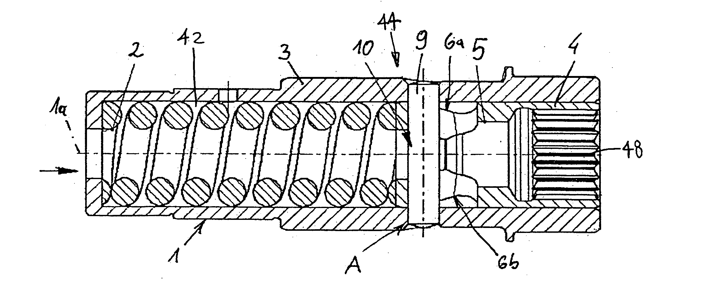
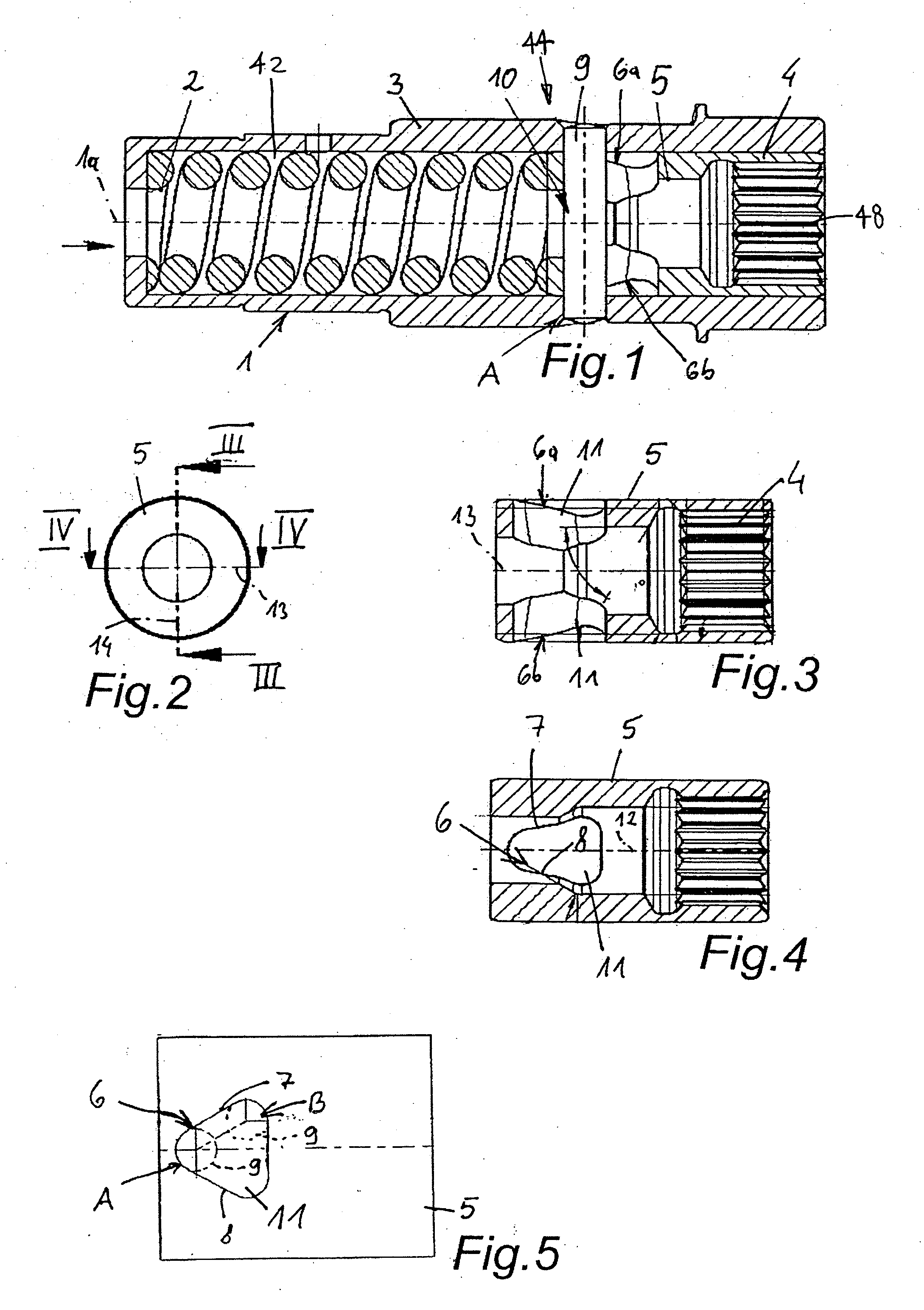
[0051] In the invention that is shown in FIGS. 1-5, the first ramp 7 and the second ramp 8 are formed by a hole 11 in the ramp body 5. The hole 11 is essentially shaped as an isosceles triangle, as can be seen in FIGS. 4-5. The ramp body 5 is loaded in the axial direction by the resilient member 2.

[0052] A pressure body 10 that is formed by a press pin 9 is connected rigidly with the first connector 3. As illustrated, the press pin 9 is transverse to the axis 1a of the torsional-vibration damper 1. The press pin 9 passes through the hole 11 in the ramp body 5, and is of a cross section that is essentially smaller than the cross section of the hole 11.

[0053] When forces are transferred uniformly, the press pin 9 is in the stable position A that is shown in FIG. 5. When in the stable position A, rotary movement is transmitted between the first connector 3 and the second connector 4 through the press pin 9 and the ramps 7, 8. Should the magnitude of the torque spike deviate from a unif...

second embodiment

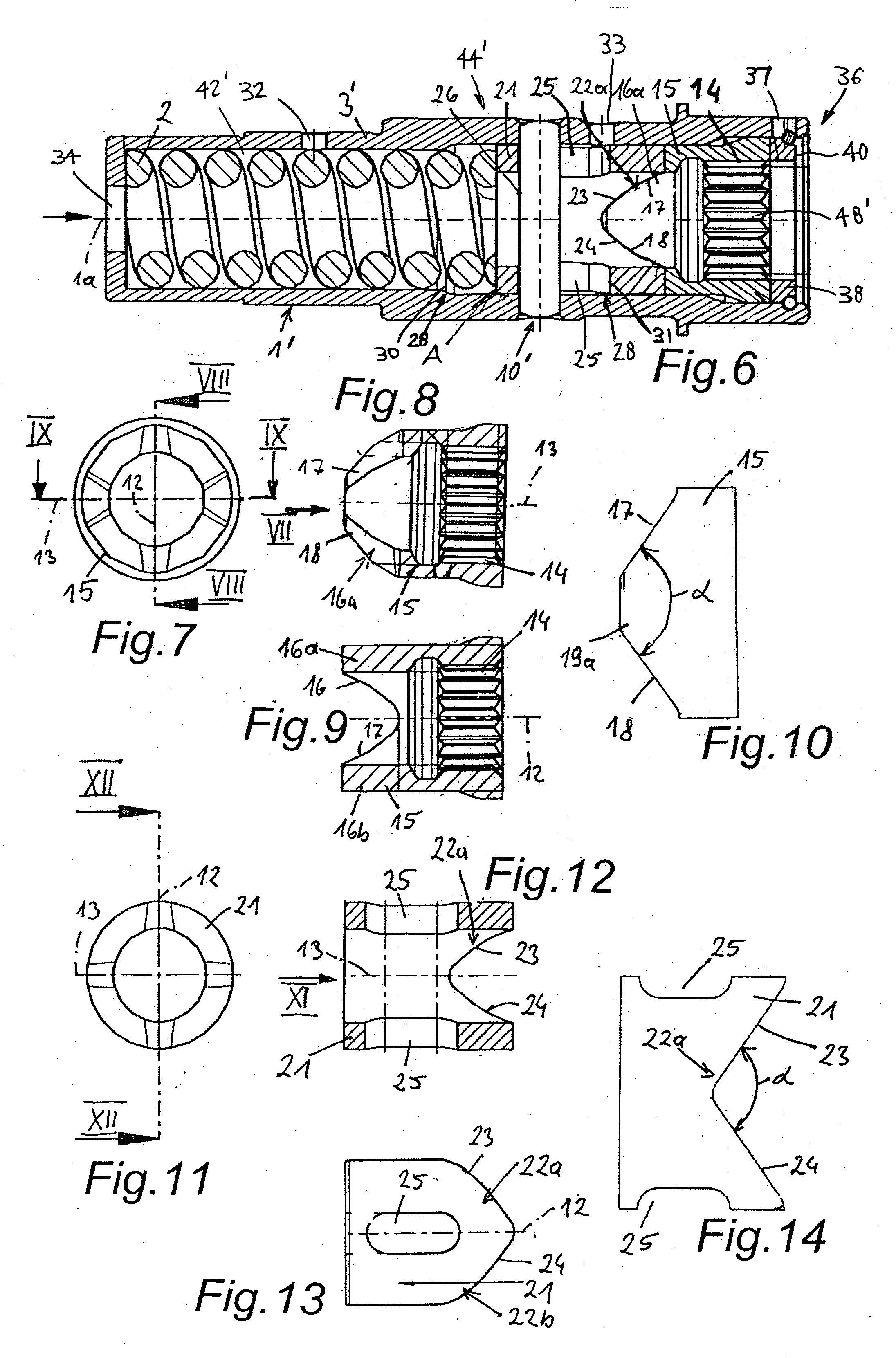
[0057] FIGS. 6-14 show a torsional-vibration damper 1'. The torsional-vibration damper 1' includes a first connector 3' and a second connector 14. This embodiment differs from the embodiment shown in FIGS. 1-5 in that a ramp unit 44' also includes a second ramp body 21, in addition to the resilient member 2 and a first ramp body 15. The first ramp body 15 essentially forms a dog clutch with the second ramp body 21. The resilient member 2 presses the second ramp body 21 against the first ramp body 15 in the axial direction.

[0058] In the embodiment illustrated in FIGS. 6-14, the first ramp body 15 has two pairs of surfaces 16a, 16b, each with a first ramp 17 and a second ramp 18. The first ramp 17 and the second ramp 18 are formed so as to be wedge-shaped to each other. The first and second ramps 17, 18 subtend an angle .alpha. of approximately 110.degree. in the developed view of the embodiment shown in FIG. 10. As discussed above, however, a wider range of angular arrangements is co...


PUM


Abstract

A torsional-vibration damper for decoupling the torsional vibration between a drive assembly and a secondary assembly is disclosed. The damper includes a first connector operatively connected to one of the assemblies, a pressure body connected to the first connector, a second connector operatively connected to the first connector permitting transmission of rotational motion therebetween, an axial displacement limiter, and a ramp unit. The ramp unit includes a resilient member and a ramp body that is connected to the second connector. The ramp body includes first and second ramps that are operatively interactive with the pressure body. The first and second ramps define a stable position when the first and second ramps and the pressure body are pressed into engagement with one another by the resilient member. The first and second connectors are rotatable with respect to one another through a predetermined angle of rotation measured from the stable position.

Description

[0001] This application relies for priority upon U.S. Provisional Application Serial No. 60 / 420,257, entitled "Vibration Decoupler," filed on Oct. 23, 2002, the disclosure of which is specifically incorporated herein by reference.[0002] 1. Field of the Invention[0003] The present invention relates to a vibration damper for decoupling torsional vibration from components that are connected to each other so as to transmit a driving force. More particularly, the present invention relates to a vibration damper for decoupling the torsional vibration of a drive assembly and a secondary assembly.[0004] 2. Description of Related Art[0005] DE 42 29 416 A1 describes a torsional-vibration damper with at least two structural elements that can rotate against the resistance of a least one helical compression spring that is pre-curved towards the axis of rotation. In each instance, the structural elements have contact areas for each end of the spring; these are used to compress the spring in the ev...

Claims


Application Information

Patent Timeline
Patent Type & Authority Applications(United States)
IPC IPC(8): F16D7/02F16F15/10F16F15/12F16F15/121F16F15/123
CPCF16F15/10F16F15/12F16F2230/0064F16F15/123F16F15/121
Inventor KUSEL, RUDOLF
Owner BOMBARDIER ROTAX
Learn More