Actuation unit for actuating a foldable wing tip portion of a wing for an aircraft

a technology of actuation unit and wing tip, which is applied in the direction of power amplification, airflow influencer, transportation and packaging, etc., can solve the problems of wing tip portion not being able to move and fix in the closed position, and wing tip portion not being able to employ an actuation unit, etc., to achieve compact and efficient design of the actuation unit, less space, and minimal toleran

Active Publication Date: 2022-05-10
AIRBUS OPERATIONS GMBH
View PDF14 Cites 0 Cited by
  • Summary
  • Abstract
  • Description
  • Claims
  • Application Information

AI Technical Summary

Benefits of technology

[0014]It is further preferred that the reduction stages are arranged on one side and the power stage is arranged on the opposite side of the offset gear, when viewed along the offset gear axis of rotation. The reduction stages are coupled to the power stage by a drive through shaft that axially proceeds through the offset gear without being coupled to the offset gear. The power stage is separately coupled to the offset gear, preferably by a coaxial shaft arranged coaxially with respect to the drive through shaft. In such a way, the offset gear is arranged in between the stages of the gear assembly, thereby allowing for a particularly compact and efficient design of the actuation unit.
[0015]According to another preferred embodiment, the gear assembly comprises a connection gear stage configured for connecting the output of the motor unit to the reduction stages when the output is not aligned with the reduction stages. In such a way, the motor unit can be arranged parallelly, and spaced apart, from the gear assembly or perpendicular to the gear assembly, such that the arrangement of actuation unit and motor unit requires less space in the axial direction.
[0016]In a preferred embodiment, the first housing part and the second housing part together enclose an interior space. The interior space is preferable sealed to the environment. The drive pinion and preferably also the offset gear are arranged inside the interior space. In such a way the toothed rack and drive pinion, and preferably also the offset gear, are protected from environmental contamination, such as dust, insects, birds, etc., so that the teeth of the toothed rack, the drive pinion and the offset gear can be formed with minimal tolerances and a high torque can be transferred.
[0017]In particular, it is preferred that a lubricant is provided inside the interior space to lubricate the toothed rack, the drive pinion and preferably the offset gear. Preferably, sealing lips are provided between the first and second housing parts in order to seal the interior space and keep the lubricant from leaking. In such a manner, the teeth of the toothed rack, the drive pinion and the offset gear can be lubricated without requiring a specific lubrication system or lubricant container.
[0018]It is also preferred that the second housing part includes a cover that is movable, in particular pivotable, between a closed position where the interior space is closed to the surrounding, and an opened position where the interior space is opened to the surrounding. By such a movable cover, the interior space can be accessed from the outside, e.g. for maintenance purposes. However, the cover might also be unmovable and fixed in the closed position, or it might be generally movable but is or can be fixed in the closed position in such a way that the cover might transfer loads, e.g. by rivets. A load bearing cover leads to further weight reduction of the second housing part and, thus, of the entire actuation unit.
[0019]It is further preferred that the first housing part forms a circumferential first case around the reduction stages and a circumferential second case around the power stage of the gear assembly. The second housing part preferably extends in the form of rotatable ring between the first case and the second case. The ring might be closed over 360° or might be opened over a certain angular range along the circumference. The first case and the second case are connected to one another by a connection structure transferring loads and torque between the first and second cases. The connection structure is arranged inside the interior space and radially surrounded by the second housing part. The connection structure is preferably formed as a curved shell part extending in parallel to the main axis of rotation and partially surrounding the offset gear. Preferably, the first case and the second case are further connected to one another by a structure bridge extending radially outwards to the second housing part. The structure bridge also serves to transfer loads between the first and second cases, and the first attachment device is mounted to the structure bridge. Preferably, rollers are mounted to the outside of the first housing part and engaging the surface of the second housing part for providing a defined and smooth path of movement for the second housing part relative to the first housing part.

Problems solved by technology

However, little available space at the wing tips and at the same time high torque requirements for the actuation of the wing tip portion do not allow to employ an actuation unit similar to the ones for moving slats or flaps of a known wing.
However, the cover might also be unmovable and fixed in the closed position, or it might be generally movable but is or can be fixed in the closed position in such a way that the cover might transfer loads, e.g. by rivets.

Method used


Image

  • Actuation unit for actuating a foldable wing tip portion of a wing for an aircraft
  • Actuation unit for actuating a foldable wing tip portion of a wing for an aircraft
  • Actuation unit for actuating a foldable wing tip portion of a wing for an aircraft

Examples


Embodiment Construction

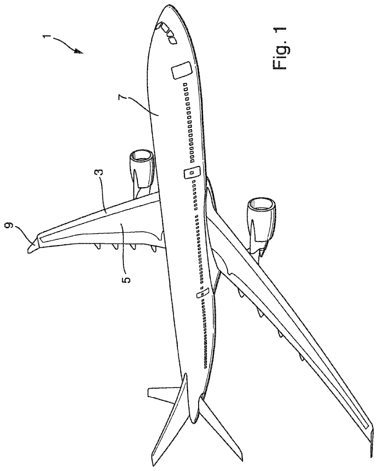
[0040]FIG. 1 shows an exemplary aircraft 1 according to an embodiment of the present invention. The aircraft 1 comprises a foldable wing 3 including a fixed wing 5 mounted to a fuselage 7, and a foldable wing tip portion 9 movably mounted to the fixed wing 5.

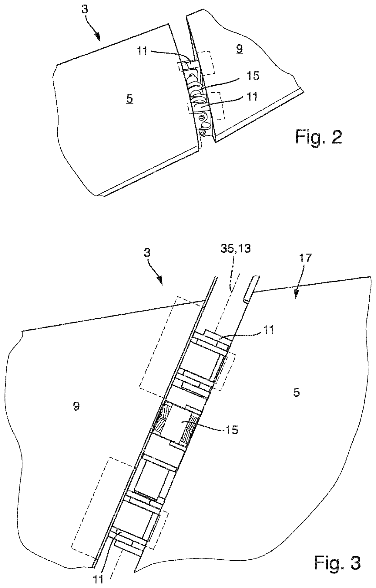
[0041]As shown in FIGS. 2 and 3, the wing 3 comprises a fixed wing 5, a foldable wing tip portion 9 mounted to the fixed wing 5 via hinges 11 rotatable about a hinge axis 13, and an actuation unit 15 for actuating movement of the wing tip portion 9 relative to the fixed wing 5, specifically folding upwards of the wing tip portion 9 relative to the fixed wing 5 about the hinge axis 13 extending in parallel to a horizontal plane and in parallel to wing surface 17.

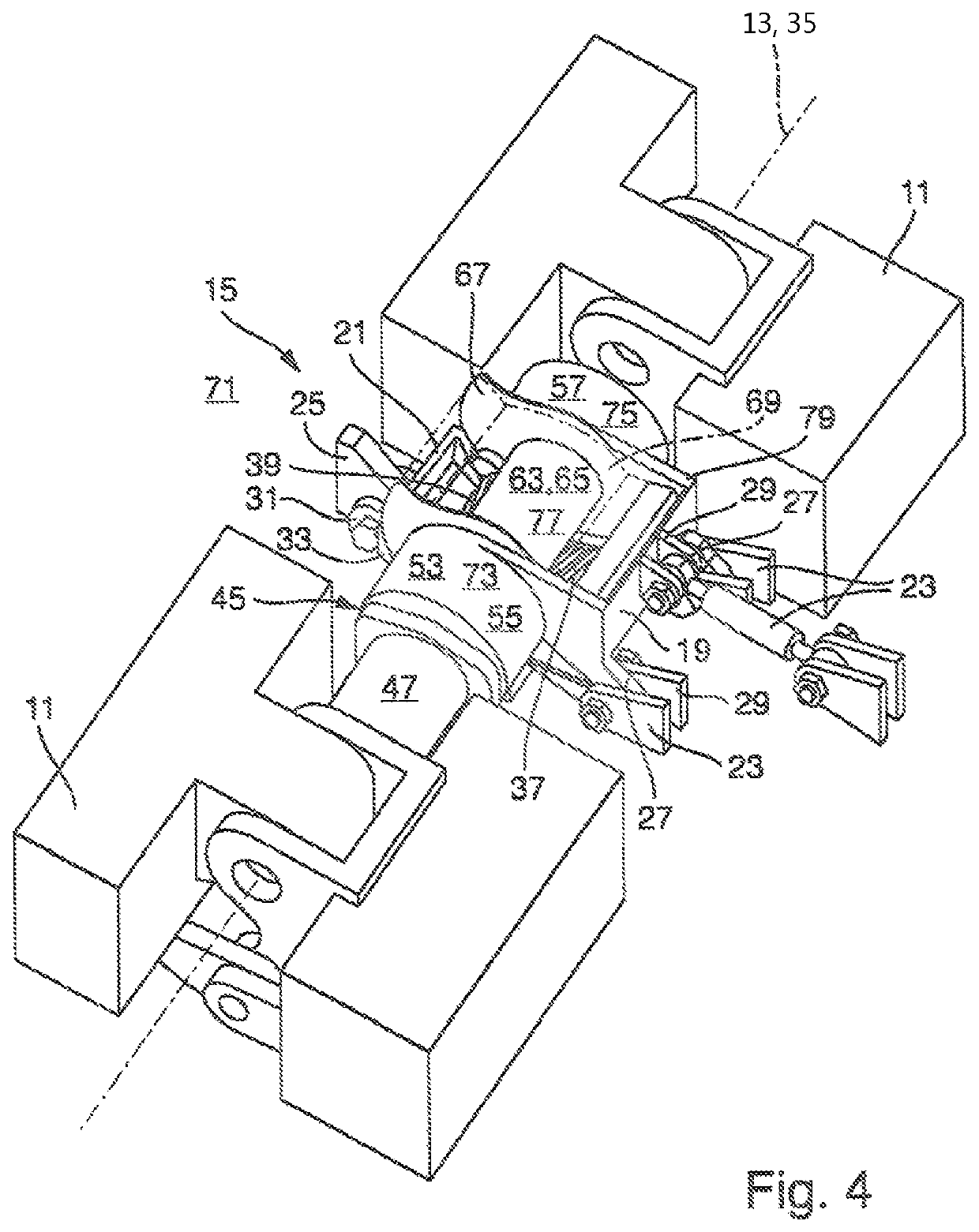
[0042]As shown in FIGS. 4 to 7, the actuation unit 15 comprises a first housing part 19 and a second housing part 21. The first housing part 19 includes a first attachment device 23 attaching the actuation unit 15 to the fixed wing 5. The first attachment device 23 compri...


PUM


Abstract

An actuation unit (15) for actuating a foldable wing tip portion (9) includes a first housing part (19) including a first attachment device (23) configured for attachment to a fixed wing (5), and a second housing part (21) including a second attachment device (25) configured for attachment to a foldable wing tip portion (9). The second housing part (21) is rotatable about a main axis of rotation (35). The second housing part (21) includes a toothed rack (37) having a concave shape and facing the main axis of rotation (35). A drive pinion (39) is supported at the first housing part (19) and engaging the toothed rack (37) for driving the second housing part (21) rotatingly relative to the first housing part (19). The drive pinion (39) is driven by a coupling arrangement (43) that is configured to be coupled to an output (45) of a motor unit (47).

Description

RELATED APPLICATIONS[0001]This application is the U.S. national phase of International Application PCT / EP2018 / 070918 filed Aug. 1, 2018, which designated the U.S. and claims priority to German Patent Application DE 10 2017 118 976.9 filed Aug. 18, 2017, the entire contents of each of which are hereby incorporated by reference.BACKGROUND AND SUMMARY OF INVENTION[0002]The present invention relates to an actuation unit for actuating a movable wing surface, in particular a foldable wing tip portion, of a wing for an aircraft. Such a wing comprises a fixed wing and a wing tip portion mounted to the fixed wing in a foldable manner. Specifically, the wing tip portion is foldable upwards about an axis extending in a horizontal plane or in parallel to a chord line or in parallel to the wing surface. Further aspects of the present invention relate to a wing comprising the actuation unit as well as an aircraft comprising the wing.[0003]Foldable wings are developed in order to reduce the space ...

Claims


Application Information

Patent Timeline
Patent Type & Authority Patents(United States)
IPC IPC(8): B64C13/34B64C3/56B64C13/50
CPCB64C13/34B64C3/56B64C13/50B64C23/072Y02T50/10
Inventor LORENZ, CHRISTIAN
Owner AIRBUS OPERATIONS GMBH
Why Eureka
Try Eureka