
Integrated circuit with interface circuitry, and an interface cell for such interface circuitry

a technology of interface circuits and integrated circuits, applied in the direction of power supply for data processing, instruments, liquid/fluent solid measurement, etc., to achieve the effects of convenient interconnection of their second supply line portion, convenient and efficient design, and improved eas

Active Publication Date: 2018-04-03
ARM LTD
View PDF14 Cites 0 Cited by
  • Summary
  • Abstract
  • Description
  • Claims
  • Application Information

AI Technical Summary

Benefits of technology

[0011]Accordingly, through use of the approach of the present invention the area associated with the power supply line structure can be significantly reduced, whilst still enabling the current carrying constraints to be met. As a result, the size of the interface cells can be reduced, hence enabling a reduction in the overall size of the integrated circuit.
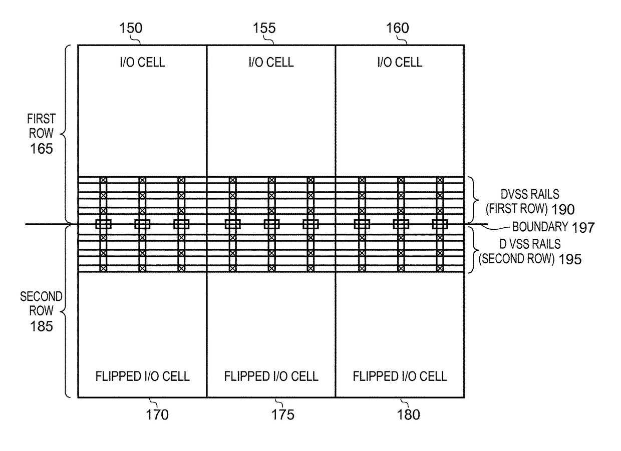
[0013]Within such embodiments, for each pair of interface cells a connection may be provided between the second supply line portions of the interface cells of the pair, such that for each interface cell in the pair the current carrying structure external to that interface cell is provided by the second supply line portion of the other interface cell in the pair. Accordingly, the second supply line arrangement provided by interconnecting the second supply line portions of the paired interface cells provides sufficient current carrying capabilities to support the current carrying constraints of the interface circuitry. Such an approach provides a particularly compact and efficient design.
[0014]There are a number of ways in which the second supply line portion of each interface cell can be configured. In one embodiment, within each pair of interface cells, the interface cells are configured such that their second supply line portion is provided adjacent said edge boundary. This improves the ease with which the second supply line portion in one interface cell can be connected to the second supply line portion in the other interface cell of the pair.
[0015]The interface cells within each pair may be configured differently so as to facilitate the interconnection of their second supply line portions. However, in one embodiment, each pair of interface cells is formed from two identical interface cells, and at the time of providing the pair of interface cells within the interface circuitry the orientation of one interface cell in the pair is flipped in the length dimension with respect to the orientation of the other interface cell of the pair, such that for both interface cells in the pair the second supply line portion is provided adjacent said edge boundary. Such an approach enables the same interface cell design to be used for both interface cells in each pair whilst still allowing the second supply line portions to be readily interconnected.
[0022]In one such embodiment, the pad access terminal is positioned between the first end and the second supply line portion, the connection path between the pad access terminal and the bump connection extends in a direction towards the functional circuitry, and the current carrying structure is provided in an area of the redistribution layer at least party overlying the second supply line portion. In such an arrangement, the area of the redistribution layer at least partly overlying the second supply line portion is not used to form the connection path between the pad access terminal and the bump connection, and accordingly the current carrying structure can readily be provided in that area without placing any additional constraints or complexity on the provision of the connection paths within the redistribution layer. Further, it is relatively straightforward to then connect the current carrying structure to the second supply line portion, for example using appropriate via connections.
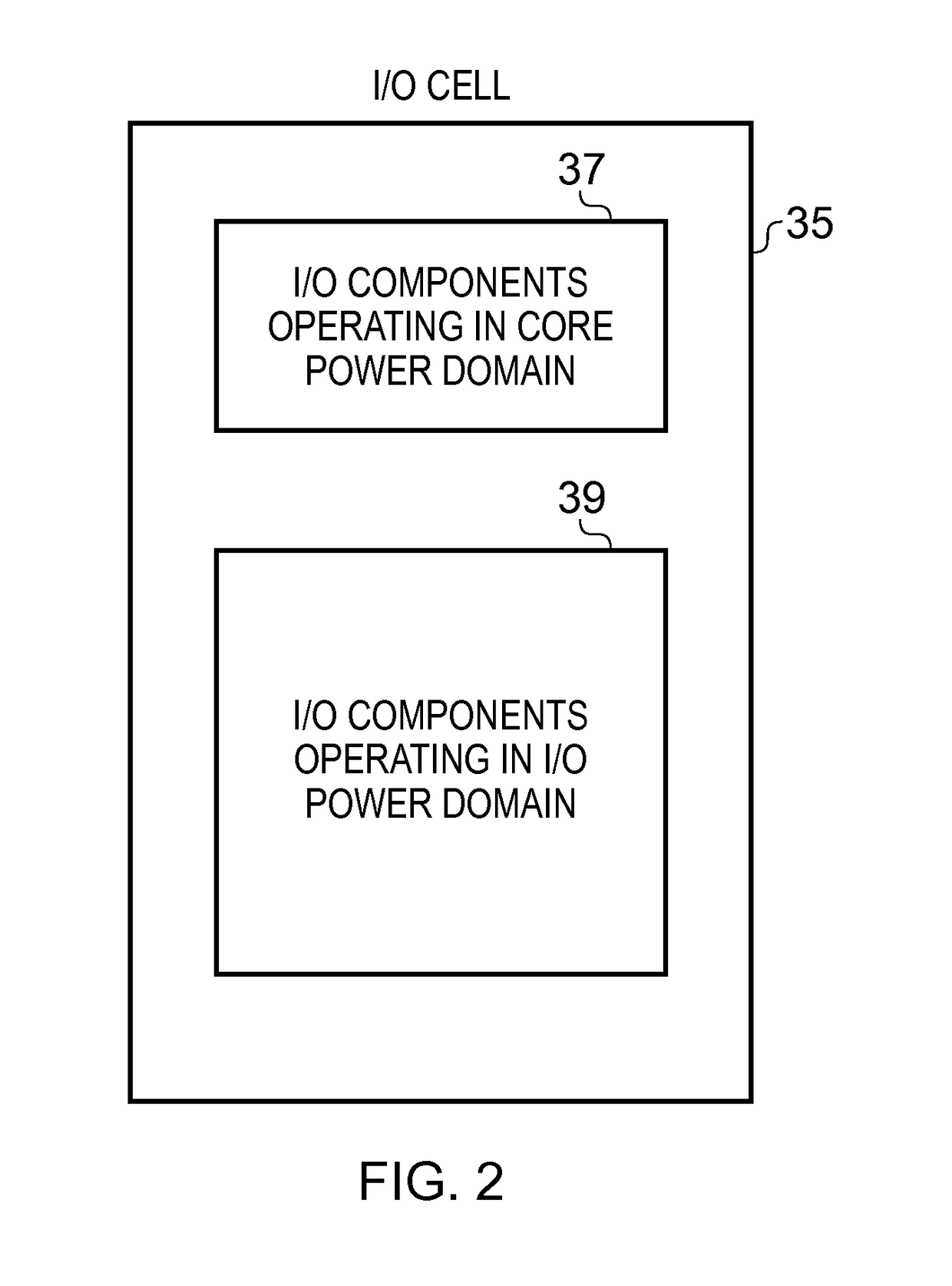
[0024]Whilst the interface circuitry is predominantly arranged to operate from a first power supply, the functional circuitry itself may operate from a different power supply, referred to herein as a second power supply. In some such embodiments, at least some of the interface cells will then comprise additional interface components configured to operate from the second power supply. In such instances, the power supply line section of each interface cell may be configured to further include supply line portions used to provide the second power supply to the additional interface components. Hence, in such embodiments the power supply line structure is required to provide multiple different power supplies, and thus the area requirements of the power supply line structure can be particularly problematic. Accordingly, in such embodiments, the use of the above described techniques is particularly beneficial, since it can enable a significant reduction in the area associated with the supply lines provided for one of the power supplies.

Problems solved by technology

In particular, the main current carrying constraint in most practical applications is that imposed by the ESD protection requirements, and although the second supply line portion by itself may not be sufficiently sized to handle such currents, in combination with the connected current carrying structure it is sized sufficiently to handle such ESD currents.

Method used


Image

  • Integrated circuit with interface circuitry, and an interface cell for such interface circuitry
  • Integrated circuit with interface circuitry, and an interface cell for such interface circuitry
  • Integrated circuit with interface circuitry, and an interface cell for such interface circuitry

Examples


Embodiment Construction

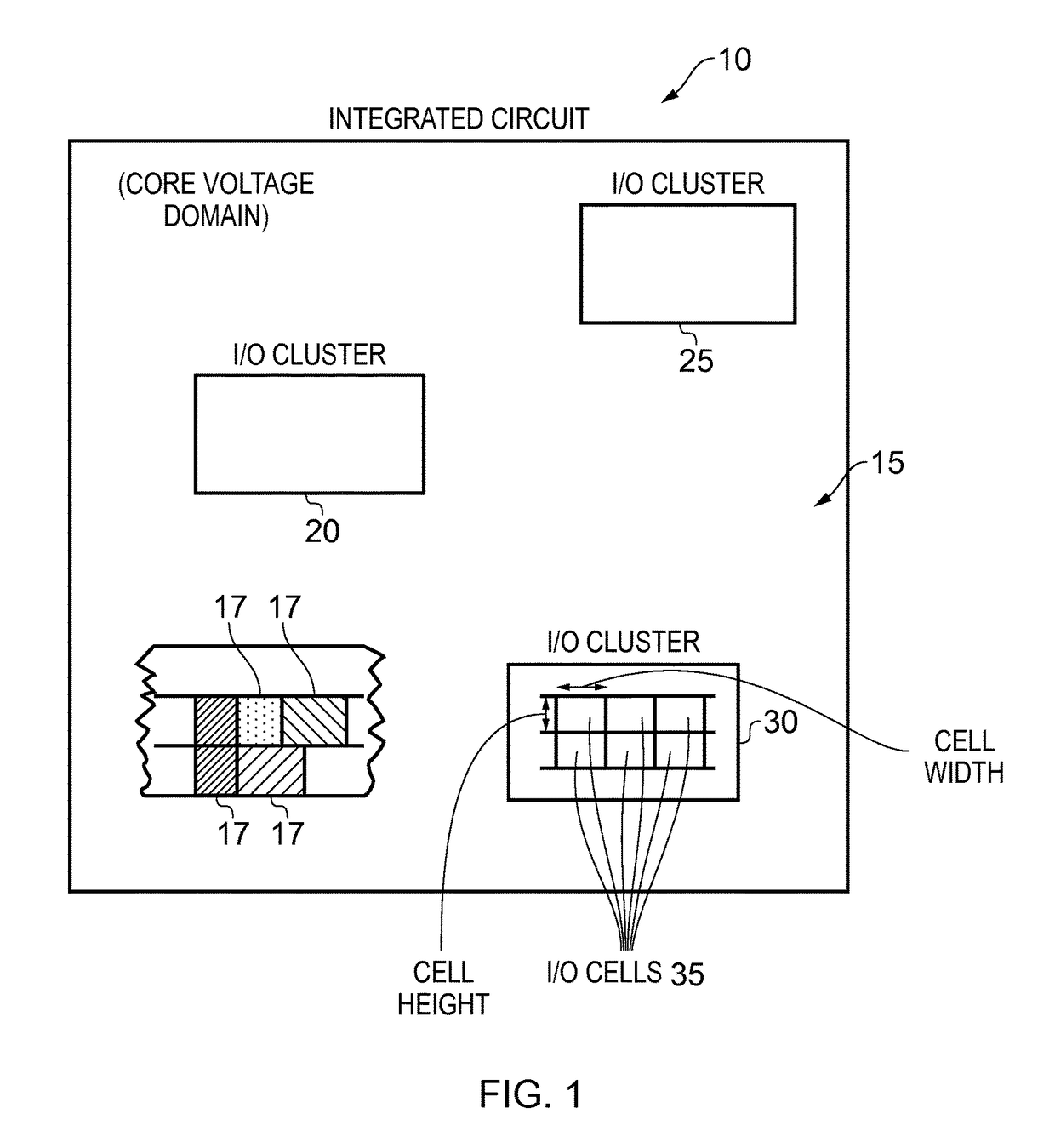
[0039]FIG. 1 schematically illustrates an integrated circuit in which the techniques of embodiments can be employed. As shown in FIG. 1, the integrated circuit 10 includes functional circuitry 15 comprising a plurality of functional components 17 that are configured to perform the required processing functions of the integrated circuit. There are a number of ways in which the individual functional components can be provided within the functional circuitry 15. For example, in accordance with one known technique, automated tools are provided which use a functional design of a planned integrated circuit (for example in the form of a gate level netlist or a Register Transfer Language higher level representation of the design) and a cell library providing a set of standard cells (standard cells defining the functional components and being “building blocks” for putting together the layout of the integrated circuit according to the functional design) in order to generate the layout of the ...


PUM


Abstract

An integrated circuit is provided with interface circuitry used to provide an interface between functional circuitry of the integrated circuit and components external to the integrated circuit. The interface circuitry includes a plurality of interface cells having interface components configured to operate from a first power supply. Each interface cell incorporates a power supply line section extending across its width and configured to cooperate with power supply line sections of other interface cells to provide a power supply line structure shared by the plurality of interface cells, for provision of the first power supply to the interface components. Each power supply line section includes a first supply line portion and a second supply line portion, the first supply line portion being sized to support a current carrying constraint of the interface circuitry, while the second supply line portion is sized insufficiently to support that current carrying constraint. Instead, each interface cell is arranged within the interface circuitry such that the second supply line portion is connected to a current carrying structure external to that interface cell, such that the second supply line portion in combination with the connected current carrying structure is sized sufficiently to support the current carrying constraint. Such an approach enables a reduction in the area required for the power supply line structure, hence enabling a reduction in the size of the interface circuitry, and accordingly a corresponding reduction in the required size of the integrated circuit.

Description

FIELD OF THE INVENTION[0001]The present invention relates to an integrated circuit with interface circuitry, and to an interface cell for such interface circuitry.BACKGROUND OF THE INVENTION[0002]Typically an integrated circuit will comprise the functional circuitry needed to perform the processing functions of the integrated circuit, along with interface circuitry (often referred to as input / output (I / O) circuitry) for providing an interface between the functional circuitry and components external to the integrated circuit. The interface circuitry will typically consist of a plurality of interface (I / O) cells used to implement the input / output requirements of the integrated circuit.[0003]Each interface cell typically incorporates a power supply line section extending across its width, and configured to cooperate with the power supply line section of other interface cells (for example by placing a plurality of interface cells side-by-side within the interface circuitry) in order to ...

Claims


Application Information

Patent Timeline
Patent Type & Authority Patents(United States)
IPC IPC(8): G06F1/00G06F1/32G06F1/26H05K9/00G06F1/18H01L23/50G06F3/047
CPCG06F1/3243G06F1/26G06F1/189G06F3/047H05K2201/10734H01L2224/16225H01L2924/15311H05K9/0039H05K2201/10522H01L23/50G11C5/14H01L23/5286H01L23/60H01L27/0248
Inventor DUBY, JEAN-CLAUDERIEN, MIKAEL
Owner ARM LTD
Learn More