Reducing image artifacts in images
Pending Publication Date: 2020-08-20
CARL ZEISS MICROSCOPY GMBH
0 Cites 0 Cited by
AI-Extracted Technical Summary
Problems solved by technology
Image artifacts can occur during image recording by means of an optical system with illumination by an illumination module.
Reflections resulting in an increased or decreased intensity in a region of a corresponding image cause a loss of information.
If the light used for illuminating (illumination) is reflected into a region of the image, e.g. the information about those regions of the sample object to be imaged which are intended to be imaged into the corresponding image region is lost as a result.
Reflections in recorded images thus impair the image impression.
Correspondingly, the image can undermodulate as a result of shading, as a result of which the image impression is also impaired.
Examples of such measures are antireflection coatings on the critical optical surfaces within the system, optical designs having increased comple...
View moreMethod used
[0055]In general, the processed images could have more than one reflection 215 and/or have more than one instance of shading 216. It would also be possible for the processed images either to have only one or more reflections or else to have only one or more instances of shading. The techniques described herein can be applied flexibly to all such scenarios in order to bring about a reduction of interference.
[0059]In general, in the various techniques described herein, a different number of images can be taken into account when determining the result image. A larger number of images may tend to enable a better reduction of interference. On the other hand, however, capturing a larger number of images can also take up a longer time duration and require more computer resources of the controller. Therefore, in the various techniques described herein, it may be worthwhile to take account of a weighing up between quality of the reduction of interference, on the one hand, and speed until provision of the result image, on the other hand, in connection with block 1003. By way of example, a fixedly predefined threshold value for the number of iterations of block 1002 could be taken into account in block 1003. It has been found, for example, that a number of 3-8 images taken as a basis for determining the result image enables a high quality of the reduction of interference, on the one hand, and does not significantly decrease the speed until provision of the result image, on the other hand.
[0061]In yet other examples, the adaptation of the arrangement for different iterations of block 1002 could be carried out by means of an optimization. By way of example, a genetic algorithm, a simplex method, a gradient method or a trust region method could be used. As a result, the comparatively large parameter space of the available arrangements 851-854 can be traversed efficiently in order to achieve a particularly good reduction of interference with a minimum number of iterations of block 1002. The abovementioned quality measure and/or a threshold value for the ...
View moreBenefits of technology
[0007]There is therefore a need for improved techniques for imaging a sample object. In particular, there is a need for apparatuses and methods which can be used to suppress reflections ...
View moreAbstract
Images are captured with a sample object in various arrangements relative to lighting and a detector. The images are then combined image point by image point on the basis of a comparison of image point values of image points of said images. This achieves a reduction in interference, i.e. reflections and/or shadows can be reduced.
Application Domain
Technology Topic
Image
Examples
- Experimental program(1)
Example
[0032]The present invention is explained in greater detail below on the basis of preferred embodiments with reference to the drawings. In the figures, identical reference signs denote identical or similar elements. The figures are schematic illustrations of various embodiments of the invention. Elements illustrated in the figures are not necessarily illustrated as true to scale. Rather, the various elements illustrated in the figures are rendered in such a way that their function and purpose become comprehensible to the person skilled in the art.
[0033]Connections and couplings between functional units and elements as illustrated in the figures can also be implemented as an indirect connection or coupling. A connection or coupling can be implemented in a wired or wireless manner.
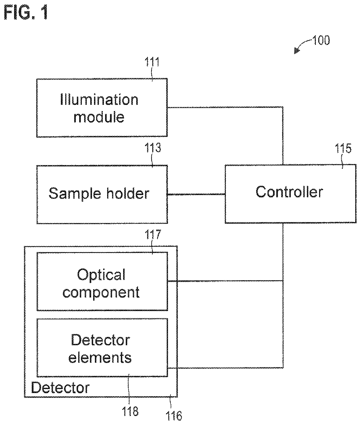
[0034]A description is given below of techniques which make it possible computationally to suppress image artifacts, that is to say in particular reflections and/or shading, during the imaging of a sample object. In this case, “reduction of interference” is understood to mean measures which make it possible to reduce the loss of information that is conventionally associated with the presence of reflections and/or shading.
[0035]FIG. 1 illustrates an exemplary optical apparatus 100. By way of example, the optical apparatus 100 in accordance with the example in FIG. 1 could implement a light microscope, for example using transmitted-light geometry or using reflection geometry. It would also be possible for the optical apparatus 100 to implement a laser scanning microscope or a fluorescence microscope. The optical apparatus 100 can enable the magnified representation of small structures of a sample object fixed by a sample holder 113.
[0036]A detector 116 is configured to generate an image of the sample object on detector elements 118, e.g. by means of a lens 117 or some other optical component. The detector 116 can thus form a camera, for example. The detector elements 118 can then be configured to capture one or more images of the sample object, in each case having a plurality of pixels. The different pixels can correspond to different detector elements 118. By way of example, a CCD or CMOS sensor can be used.
[0037]An illumination module 111 is configured to illuminate the sample object fixed on the sample holder 113. The illumination module 111 can be configured, in particular, to enable an angle-variable illumination of the sample object. This means that the illumination module 111 can be configured optionally to illuminate the sample object from different illumination directions or generally to implement different illumination geometries: different illuminations can thus be implemented as a result. To that end, the illumination module 111 could have a multiplicity of light sources, for example, which can be drivable separately—i.e. can be switched on and off separately from one another. Other implementations of the illumination module 111 could also be chosen, for example a micro mirror device (digital micro mirror device, DMD) or a scanner.
[0038]A controller 115 is provided to drive the various components 111-114 of the optical apparatus 100. By way of example, the controller 115 could be implemented as a microprocessor or microcontroller. As an alternative or in addition thereto, the controller 115 could comprise an FPGA or ASIC, for example. The controller 115 could for example load program code from a memory (not illustrated in FIG. 1).
[0039]By way of example, the controller 115 could be configured to drive a motor of the sample holder 113 to alter the arrangement of the sample object relative to the detector 116 and/or to alter the arrangement of the sample object relative to the illumination module 111—and thus the illumination. It would also be possible for the controller 115 to be configured to drive a motor of the sample holder 113: by this means, too, it is possible to alter the arrangement of the sample object relative to the detector 116. The controller can furthermore be configured to drive the illumination module 111 for altering the illumination, e.g. by choosing different illumination geometries: by this means, too, it is possible to alter the arrangement of the sample object relative to the illumination.
[0040]The optical system 100 is thus configured to set flexibly a relative arrangement between sample object, firstly, and illumination by the illumination module 111 and/or the detector 116. In this case, in principle, it is possible to use different techniques alone or in combination in order to vary said arrangement.
[0041]A first technique comprises using different illuminations. To that end, the controller can drive the illumination module 111 in a suitable manner. To that end, by way of example, the illumination module 111 could be adjusted mechanically in order thereby to implement different illumination directions. By way of example, a lateral displacement perpendicularly to the beam path could be implemented. In such a scenario, different positions of the illumination module 111 correspond to different relative arrangements of the sample object with respect to the illumination. In another variant, however, the illumination module 111 could also have a plurality of light sources, such that different illumination geometries can be implemented by driving different light sources. The illumination can be varied by this means, too. Different relative arrangements of the sample object with respect to the illumination can be implemented by the use of different illuminations.
[0042]A second technique comprises using an adjustable sample holder 113. By way of example, it would be possible for a motor to be provided, which adjusts the sample holder 113—and thus the sample object fixed by the sample holder 113—relative to the illumination by the illumination module 111 and/or relative to the detector 116. By way of example, a lateral displacement perpendicularly to the beam path could be implemented. Different positions of the sample holder 113 then correspond to different relative arrangements between firstly the sample object and secondly illumination by the illumination module 111 and the detector 116.
[0043]A third technique, finally, comprises using an adjustable detector 116. By way of example, the optical component 117 could be adjustable and/or the detector elements 118 could be adjustable. By way of example, a lateral displacement perpendicularly to the beam path could be implemented. By way of example, it would be possible for a motor to be provided, which adjusts the detector 116—relative to the sample holder 113 and the illumination module 111. Different positions of the detector 116 then correspond to different relative arrangements between firstly the sample object and secondly the detector 116.
[0044]FIG. 2 illustrates aspects in relation to the illumination module 111. In the exemplary implementation in accordance with FIG. 2, the illumination module 111 comprises a carrier 120, on which a multiplicity of light sources 121—for example light emitting diodes—are arranged. In the example in FIG. 2, the light sources 121 are arranged in a lattice structure. In other examples, however, the light sources 121 could also be arranged on the carrier 120 in a different way, for example in a ring-shaped manner, etc. By way of example, the light sources 121 could be arranged around a lens in a ring-shaped manner, i.e. a so-called LED ring light can be used.
[0045]The controller 115 can be configured to drive individual light sources 121 separately, i.e. to switch individual light sources 121 on and off separately. By virtue of one specific light source 121 being switched on and the remaining light sources 121 being switched off, it is possible to implement the illumination of the sample object with a specific illumination direction. However, it would also be possible for a specific illumination direction to be implemented by switching on more than one light source 121. By way of example, two or more adjacent light sources 121 could be switched on. In this way, in general, the illumination geometry of the illumination of the sample object can be varied. In particular, it is thus possible to vary the relative arrangement of the sample object relative to the illumination.
[0046]The illumination module 111 could have further optical elements, for example a condenser lens element, etc. This is not illustrated in FIG. 2 for reasons of simplicity.
[0047]FIG. 3 is a flowchart of one exemplary method. By way of example, the controller 115 could be configured to carry out the method in accordance with the example in FIG. 3. By way of example, to that end, the controller 115 could load program code from a memory and then execute it.
[0048]Firstly, capturing a first image of the sample object is carried out in block 1001. To that end, for example, the detector elements 118 could be driven. The image can have a plurality of pixels corresponding respectively to a measurement signal of the various detector elements 118. In block 1001, the first image is captured for a first arrangement of the sample object with respect to the illumination and with respect to the detector.
[0049]This can comprise choosing the first arrangement in a targeted manner, for example by means of one or more of the following techniques: (I) predefining the illumination in a targeted manner, for example by predefining a specific illumination geometry for instance by means of the use of one or more light sources from a multiplicity of light sources, cf. FIG. 2; (II) predefining the position of the sample object in a targeted manner, for example by driving a motor of a sample holder, such that the latter assumes a specific position; and/or (III) predefining the position of the detector in a targeted manner, for example by driving a motor that adjusts the detector elements and/or some other optical component of the detector.
[0050]The targeted predefinition of the illumination 119 by using different illumination geometries is illustrated e.g. in FIGS. 4 and 5, wherein the different illumination geometries 801, 802 (implemented by different illumination directions in the example in FIGS. 4 and 5) could be produced e.g. by driving different light sources 121 in a scenario in accordance with FIG. 2. The targeted predefinition of the position of the detector elements 118 is illustrated e.g. in FIG. 6. This corresponds to positioning the detector 116. Finally, the targeted predefinition of the position of the sample object 210 is illustrated in FIG. 7. By way of example, in FIG. 6, the detector elements 118 are displaced relative to the scenario in FIG. 7; correspondingly, in FIG. 7, the sample object 210 is displaced relative to the scenario in FIG. 6. In FIGS. 4-7, the optical axis 290 is illustrated as a reference in order to enable a comparison of the FIGs. It is evident from a comparison of FIGS. 4-7 that the arrangement 851-854 of the sample object 210 with respect to the illumination 119 and with respect to the detector 116 can be varied partly or fully circumferentially in this way.
[0051]Referring once again to FIG. 3: a second image of the sample object is then captured in block 1002. To that end, the detector elements 118 could once again be driven, for example. The second image from block 1002 can also have a plurality of pixels. The second image is captured in block 1002 for a second arrangement of the sample object with respect to the illumination and/or with respect to the detector elements, said second arrangement being at least partly different than the first arrangement in block 1001. This can in turn be done by predefining the second arrangement in a targeted manner, wherein one or more of the techniques which were described above in relation to block 1001 can also be used (cf. also FIGS. 4-7).
[0052]This means that by carrying out blocks 1001 and 1002, therefore, a first image of the sample object is obtained for a first arrangement of the sample object with respect to the illumination and/or with respect to the detector, and a second image of the sample object is obtained for a second arrangement of the sample object with respect to the illumination and/or with respect to the detector, said second arrangement being at least partly different than the first arrangement.
[0053]As a result, it is possible to achieve an effect illustrated in association with FIGS. 8 and 9.
[0054]FIG. 8 illustrates an image 201 that was captured for an arrangement 851 between the sample object 210 and the illumination 119 and also the detector 116. The image 201 includes a reflection 215. The reflection 215 partly overlaps the image of the sample object 210, for which reason a loss of information is present. In addition, the image 201 also includes a shading 216.
[0055]In general, the processed images could have more than one reflection 215 and/or have more than one instance of shading 216. It would also be possible for the processed images either to have only one or more reflections or else to have only one or more instances of shading. The techniques described herein can be applied flexibly to all such scenarios in order to bring about a reduction of interference.
[0056]FIG. 8 also illustrates an image 202 that was captured for the arrangement 852 between the sample object 115 and the illumination 119 and also the detector 116. In comparison with the image 201, in this case, therefore, the illumination geometry 801, 802 and hence the illumination 119 were varied, but the position of the detector 116 and the position of the sample holder 113 and thus of the sample object 215 were not altered (cf. FIGS. 4 and 5). Therefore, the position of the image of the sample object 215 does not change between the images 201 and 202; however, the position of the reflection 215 and of the shading 216 does change. This effect can be utilized to implement the reduction of interference.
[0057]FIG. 8 finally also illustrates an image 203, captured for the arrangement 853 or the arrangement 854 between the sample object 115 and the illumination 119 and also the detector 116. In comparison with the image 201, the illumination geometry 801, 802 was not varied in this case, and so the same illumination 119 is used. However, the position of the detector 116 relative to the position of the sample holder 113 was altered—by adjusting the detector 116, i.e. in particular the detector elements 118, and/or the sample holder 113, cf. FIGS. 6 and 7. Therefore, the position of the image of the sample object 210 changes; the position of the reflection 215 and the position of the shading 116 remain unchanged, however. This effect can also be utilized to implement the reduction of interference.
[0058]Referring once again to FIG. 3: block 1003 is then carried out. Block 1003 is optional. Block 1003 involves checking whether a further second image is intended to be captured for a further arrangement of the sample object with respect to the illumination and/or with respect to the detector. If this is the case, block 1002 is carried out again, wherein the arrangement of the sample object with respect to the illumination and with respect to the detector can be varied again. Otherwise, block 1004 is carried out.
[0059]In general, in the various techniques described herein, a different number of images can be taken into account when determining the result image. A larger number of images may tend to enable a better reduction of interference. On the other hand, however, capturing a larger number of images can also take up a longer time duration and require more computer resources of the controller. Therefore, in the various techniques described herein, it may be worthwhile to take account of a weighing up between quality of the reduction of interference, on the one hand, and speed until provision of the result image, on the other hand, in connection with block 1003. By way of example, a fixedly predefined threshold value for the number of iterations of block 1002 could be taken into account in block 1003. It has been found, for example, that a number of 3-8 images taken as a basis for determining the result image enables a high quality of the reduction of interference, on the one hand, and does not significantly decrease the speed until provision of the result image, on the other hand.
[0060]In other examples, a quality measure could also be checked online in block 1003: to that end, the combination of the various images for generating the result image could at least partly be carried out beforehand in order to ascertain the quality measure. If the quality measure indicates a sufficiently high quality of the result image in connection with the reduction of interference, carrying out further iterations of block 1002 can be terminated.
[0061]In yet other examples, the adaptation of the arrangement for different iterations of block 1002 could be carried out by means of an optimization. By way of example, a genetic algorithm, a simplex method, a gradient method or a trust region method could be used. As a result, the comparatively large parameter space of the available arrangements 851-854 can be traversed efficiently in order to achieve a particularly good reduction of interference with a minimum number of iterations of block 1002. The abovementioned quality measure and/or a threshold value for the number of iterations could serve as a termination criterion. In this case, such a flexible variation of the arrangement 851-854 for the various images taken into account is not necessary in all examples, however: e.g. in general it would also be possible for a fixedly predefined number of arrangements 851-853 to be processed successively. Combining the first image from block 1001 and the one or more second images from one or more iterations of block 1002 pixel by pixel is carried out in block 1004. A result image having the image artifacts reduced is obtained as a result. The result image can thus have a particularly high image quality.
[0062]Combining pixel by pixel can mean that the pixel values of the various images are combined differently, depending on the pixel. By way of example, in the result image for a first pixel the pixel value of the first image could be taken into account, but not the assigned pixel value of the second image; by contrast, in the result image for a second pixel the pixel value of the first image could not be taken into account, but the pixel value of the assigned pixel of the second image could be taken into account. A pixel-dependent weighting of the pixel values of the various images would also be conceivable. In general, different pixels are thus treated differently during the process of combining pixel by pixel.
[0063]The process of combining pixel by pixel can make it possible for that or those pixel value(s) not corrupted by image artifacts 215, 216 to be taken into account in each case. A result image 250 having no or no significant reflections 215 and/or instances of shading 216 is obtained as a result; see FIG. 9. FIG. 9 illustrates the result image 250 obtained from the combination of the images 201-203 pixel by pixel. Said result image shows the sample object 210, but not the image artifacts 215, 216. A corresponding technique is illustrated in association with FIG. 10.
[0064]FIG. 10 is a flowchart of one exemplary method. For example, the method in accordance with FIG. 10 could be carried out in association with block 1004 of the method in FIG. 3. The method in accordance with FIG. 10 makes it possible to combine pixel by pixel a plurality of images having at least partly different arrangements of the sample object with respect to the illumination and with respect to the detector.
[0065]Firstly, registration of the different images is carried out in block 1011. In principle, block 1011 is optional. The registration of the different images makes it possible to obtain an assignment between pixels of the different images. What can be achieved in this way is that pixels which include the same information content in different images are assigned to one another. Pixels which image the same region of the sample object 210 can thus be assigned to one another. In particular, such an assignment can be ensured even if the image of the sample object is contained at different positions in the different images (cf. FIG. 8, images 201 and 203). Conventional registration techniques can be used. In the various examples described herein, the registration can comprise a translation and/or a compression and/or a rotation and/or a distortion.
[0066]An assignment between the pixels of the different images is obtained by means of the registration in block 1011. If block 1011 is not carried out, a simple one-to-one assignment of the pixels of the different images can be used, i.e. pixels obtained by the same detector element can be assigned to one another.
[0067]A set of assigned pixels is then selected in block 1012. The set selected in block 1012 includes as many elements as there are images (hereinafter n elements). This corresponds to the number of iterations of block 1002, cf. FIG. 3.
[0068]By way of example, FIG. 11 illustrates, for a scenario where n=6, the pixel values 261-266 for a set of assigned pixels from images with various arrangements 851-854. It is evident from the example in FIG. 11 that—although the assigned pixels of a set should have the same information content—the pixel values vary significantly. This variation of the pixel values 261-266 can occur on account of the image artifacts.
[0069]In general, in the various examples described herein, different information can be coded by the pixel values. By way of example, a brightness and/or a color could be coded by the pixel values. If a brightness, for example, is coded by the pixel values, then the pixel value 261 could indicate a particularly high brightness; this can be an indication that the pixel value 261 is caused on account of a reflection 215. Correspondingly, the pixel value 264 indicates a particularly low brightness; this can be an indication that the pixel value 264 is caused on account of a shading 216. These findings can be used to implement the reduction of interference.
[0070]To that end, it may be possible, in general, to compare the various pixel values 261-266 of assigned pixels with one another. This comparison can be taken into account when combining the images. By way of example, particularly large or particularly small, i.e. in general non-extremal, pixel values can be identified in this way. In the various examples described herein, it is generally possible to use one or more non-extremal pixel values when combining the images for the respective pixel, while one or more extremal pixel values can be discarded before the combining.
[0071]One possibility for implementing the comparison comprises the analysis of the distribution of the pixel values 261-266 of assigned pixels of the various images. By way of example, the slopes of the distribution could be truncated. This can be achieved e.g. in a simple manner by means of sorting the pixel values 261-266. By way of example, FIG. 12 illustrates the sorted distribution 279 of the pixel values 261-266 from FIG. 11.
[0072]Referring once again to FIG. 10: in order to implement the reduction of interference, it is thus possible to carry out a process of sorting the pixel values for the current set of assigned pixels. The sorting can be carried out for example from large pixel values toward small pixel values.
[0073]Then, in block 1014, it is possible to discard the extremal pixel values from the current set of assigned pixel values. In the scenario in FIG. 12, this means that only the pixel values within the central region 271 are retained, but the extremal pixel values 261 and 264 are discarded. This corresponds to truncating the slopes of the distribution 279. For example, in general, the o largest and/or the p smallest pixel values could be discarded (wherein n−o+p>0 in order that at least one pixel value remains). What can be achieved as a result is that such pixel values 261, 264 which are highly likely to be corrupted by image artifacts 215, 216 do not exert any influence on the result image 250. This makes it possible to suppress the interference structure.
[0074]In block 1015 in FIG. 10, finally, the averaging of the pixel values that have not been discarded is carried out, i.e. in the scenario in FIG. 12 the average value 272 of the pixel values 262, 263, 265, 266 in the central region 271 of the sorted distribution is determined. The discarded, extremal pixel values 261, 264 are ignored when determining the average value.
[0075]Such techniques illustrated in association with FIGS. 10-12 can be varied in other examples. By way of example, a median over all the various pixel values of assigned pixels of the different images could also be determined, as a result of which extremal pixel values 261, 164 would be represented in the result image to a lesser extent than non-extremal pixel values. A weighted averaging would also be possible. In all such examples, the comparison of the pixel values 261-266 makes it possible to identify extremal pixel values. This makes it possible particularly robustly to identify those images in which a specific imaged region is corrupted by an image artifact 215, 216.
[0076]In summary, a description has been given above of techniques which enable a reduction of interference by means of digital postprocessing of a plurality of captured images. By way of example, the digital postprocessing can be configured to carry out an “on-the-fly” reduction of interference. That is to say that a latency between image capture and display with reduction of interference can be for example less than 1 second or optionally less than 500 ms. Such short latencies can be achieved, in particular, if use is made of different illuminations by use of an array of light emitting diodes for the variation of the arrangement. In order to implement the reduction of interference, in this case the relative arrangement between firstly sample object and secondly illumination and detector can be varied at least partly from image to image. What is achieved as a result is that in the different images different regions are influenced by the image artifacts. What can then be achieved by combining the different images pixel by pixel is that a result image is obtained which has no or only a reduced number of image artifacts.
[0077]Techniques described herein make it possible, in particular, to implement the reduction of interference particularly flexibly. In particular, it is possible to eliminate a limitation for example with regard to the choice of the different illuminations in comparison with reference implementations: for example, it is also possible to use adjacent illumination directions for implementing different illuminations, without this necessarily resulting in a poorer reduction of interference. By way of example, it is also possible to remove image artifacts which still overlap when adjacent illumination directions are used. By way of example, it is also possible to use different brightnesses for the different illuminations: by suitably combining the various images, for example by averaging and/or comparing the pixel values of assigned pixels, it is possible to take account of variations of the brightness of the illumination.
[0078]The techniques described herein can be used in various fields of application. One example concerns, for instance, the reduction of interference in microscopy with an LED ring light having separately drivable LEDs. A further example concerns e.g. medical equipment for examining eyes: for instance, a slit lamp with an additional lens in front of the eye and changing illumination directions could be used in this case. A further example concerns e.g. application in materials testing or production testing, e.g. in association with printed circuit boards, etc.
[0079]While exemplary embodiments have been described with reference to the figures, modifications can be realized in further exemplary embodiments.
[0080]While the image recording apparatus according to exemplary embodiments can, in particular, be a microscope system, the techniques described can also be used in other imaging systems.
Login to view more PUM


Description & Claims & Application Information
We can also present the details of the Description, Claims and Application information to help users get a comprehensive understanding of the technical details of the patent, such as background art, summary of invention, brief description of drawings, description of embodiments, and other original content. On the other hand, users can also determine the specific scope of protection of the technology through the list of claims; as well as understand the changes in the life cycle of the technology with the presentation of the patent timeline. Login to view more.
Login to view more Similar technology patents
Computational selection of probes for localizing chromosome breakpoints
InactiveUS20080044916A1Good resolutionPrevent and reduce cross hybridizationSugar derivativesMicrobiological testing/measurementGenomic intervalHybridization probe
Owner:ROGAN PETER +1
Flexographic printing original plate capable of being laser-engraved
ActiveUS20110083571A1Good ink transfer and printing durabilityGood resolutionPlate printingFoil printingFlexographyChemistry
Owner:TOYO TOYOBO CO LTD
Alkali developable photosensitive resin composition and dry film manufactured by the same
ActiveUS20100113640A1Good resolutionExcellent heat resistance and dielectric propertiesImpression capsOrganic chemistryDouble bondAqueous solution
Owner:LG CHEM LTD
Solder resist composition and printed-circuit board
InactiveCN102844711AImprove acid resistanceGood resolutionPrinted circuit aspectsPhotosensitive materials for photomechanical apparatusSolder maskResist
Owner:TAIYO INK MFG
Capacitor appearance detection device and method based on artificial intelligence technology
PendingCN112083002AReduce difficultyGood resolutionOptically investigating flaws/contaminationSortingCapacitance meterArtificial neuronal network
Owner:SUZHOU CASIA ALL PHASE INTELLIGENCE TECH CO LTD
Classification and recommendation of technical efficacy words
- Good contrast
- Good resolution
Fingerprint reading device and personal verification system
InactiveUS20050123176A1Good contrastReduce influenceImage analysisSolid-state devicesPhysicsVerification system
Owner:CANON KK
Double-frequency laser interferometry apparatus
InactiveCN101413783AAvoid frequency aliasingGood contrastUsing optical meansOptical pathOpto electronic
Owner:BEIJING CHANGCHENG METERING TEST TECH INST NO 1 GRP CO CHINA AVIATION IND
Liquid Crystal Display Device
InactiveUS20120242925A1Good contrastIncrease in costNon-linear opticsImage contrastLiquid-crystal display
Owner:JAPAN DISPLAY INC
Panoramic Image Preparing Method And Three-Dimensional Laser Scanner
ActiveUS20120229870A1Optimize contrastGood contrastCharacter and pattern recognitionElectromagnetic wave reradiationComputer visionComputer graphics (images)
Owner:KK TOPCON
Optical compensator for liquid crystal display
ActiveUS20050190327A1Good contrastPolarising elementsTemporary pavingsChemistryLiquid-crystal display
Owner:INNOLUX CORP
System for medical examination or treatment
ActiveUS20050101859A1Good resolutionWell checkUltrasonic/sonic/infrasonic diagnosticsSurgeryIntravascular ultrasoundFiber
Owner:SIEMENS HEALTHCARE GMBH
Thin planar switches and their applications
InactiveUS20060250534A1Good resolutionGood optical efficiencyStatic indicating devicesSolid-state devicesElectric fieldLiquid crystal
Owner:CITALIA LTD
Diamond marking
InactiveUS6391215B1Good resolutionControl depthBranding equipmentCellsElectrically conductiveGemstone
Owner:DE BEERS UK LTD
Multicolor staring missile sensor system
InactiveUS6946647B1Good resolutionGood sensitivityTelevision system detailsRadiation pyrometryMissileSensor system
Owner:RAYTHEON CO
Recording device and recording method
InactiveUS20050083414A1Good resolutionTelevision system detailsElectronic editing digitised analogue information signalsRecording formatJpeg encoder
Owner:SONY CORP