
Artificial epidermis structure

a technology of artificial epidermis and structure, applied in the field of artificial epidermis structure, can solve the problem of limited variation of frictional force acting on the target object from the artificial skin, and achieve the effect of reducing the range of frictional force variations

Active Publication Date: 2020-08-27
HONDA MOTOR CO LTD
View PDF4 Cites 0 Cited by
  • Summary
  • Abstract
  • Description
  • Claims
  • Application Information

AI Technical Summary

Benefits of technology

The patent describes an artificial epidermis that can expand its range of variations in the amount of friction it applies to an object.

Problems solved by technology

Therefore, a range of variation forms of a frictional force acting on the target object from the artificial skin is limited.

Method used


Image

  • Artificial epidermis structure
  • Artificial epidermis structure

Examples


first embodiment

(Configuration)

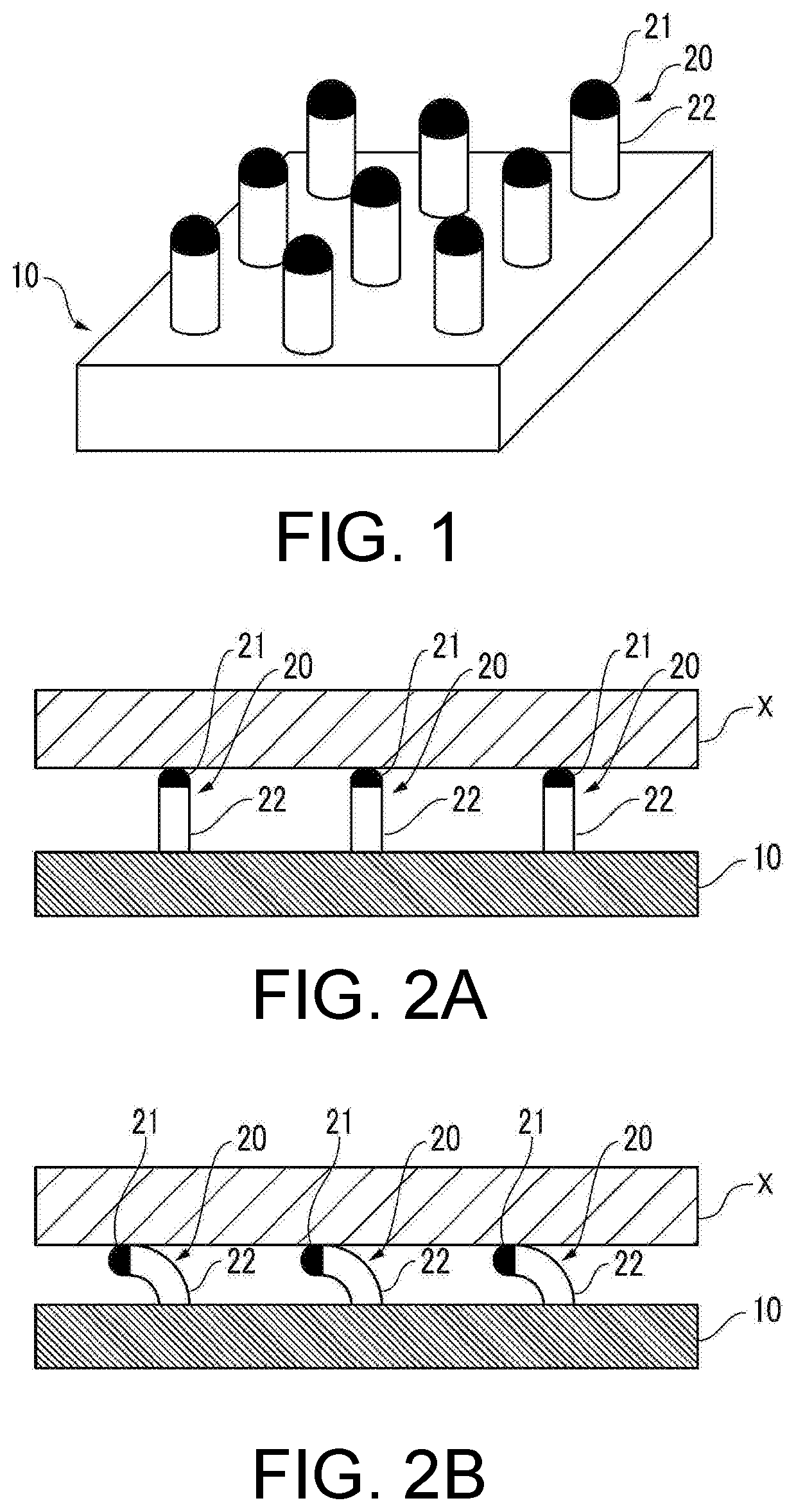
[0026]An artificial epidermis structure used as a first embodiment of the disclosure shown in FIG. 1 includes a base body 10 and a plurality of protrusions 20 protruding from the surface of the base body 10. The protrusion 20 includes a distal end portion 21 (upper portion) and a base portion 22 (lower portion). FIG. 1 is a schematic diagram, and respective aspect ratio of the base body 10 and the protrusion 20, a ratio of the arrangement interval of the plurality of protrusions 20 with respect to the size of the protrusion 20, a size ratio of the distal end portion 21 and the base portion 22 of the protrusion 20 and the like are different from an actual artificial epidermis structure (the same also applies to FIG. 2 and the like).

[0027]The surface of the base body 10 may have a curved shape in addition to a substantially plane shape. The direction in which the protrusion 20 protrudes from the surface of the base body 10 may be parallel or inclined with respect to a n...

second embodiment

(Configuration)

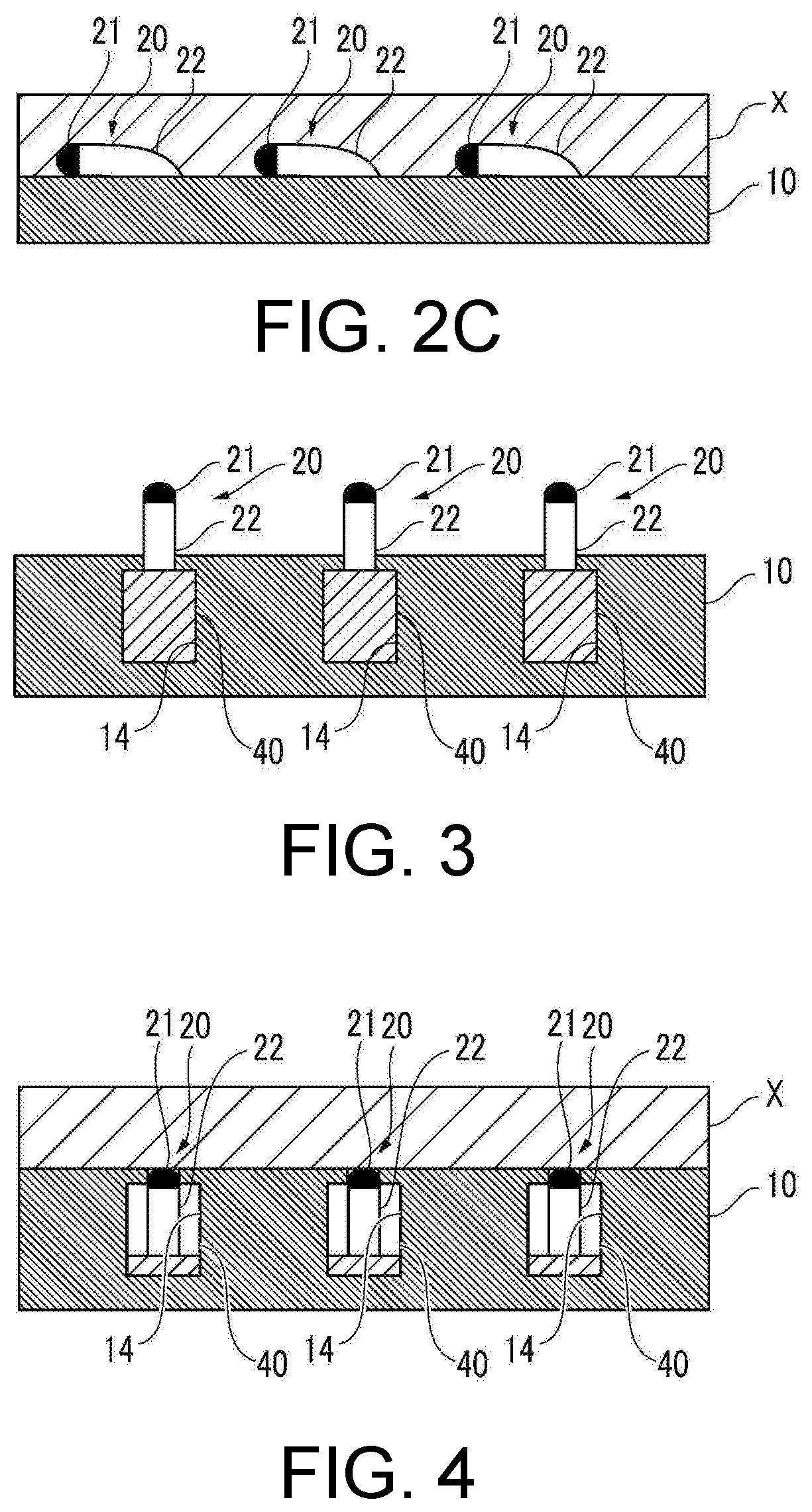
[0042]In an artificial epidermis structure used as a second embodiment of the disclosure shown in FIG. 3, at least some protrusions 20 of the plurality of protrusions 20 are configured to be capable of at least partially sinking with respect to the base body 10 so that the protrusion amount of the at least some protrusions 20 from the surface of the base body 10 is reduced. Specifically, an internal space 14 used as a half-open space having an opening portion on the surface of the base body 10 is formed in an outer-layer portion of the base body 10. An elastic member 40 is accommodated in the internal space 14, and a base end portion of the protrusion 20 is joined to the elastic member 40 through the opening portion of the internal space 14. The elastic member 40 is configured, for example, by an elastic material such as a porous sponge, a silicone rubber or the like.

[0043]The other configurations of the artificial epidermis structure of the second embodiment are subs...


PUM

PropertyMeasurementUnit
aspect ratioaaaaaaaaaa
friction coefficientaaaaaaaaaa
pressureaaaaaaaaaa

Abstract

Provided is an artificial epidermis structure. Three different contact states can be realized between the artificial epidermis structure and a target object. The “first contact state” is a state in which only the surface of a distal end portion of each protrusion contacts the target object. The “second contact state” is a state in which each protrusion tilts with respect to a base body corresponding to the force received from the target object and thereby the surface of a base portion and the surface of the distal end portion of each protrusion contact the target object. The “third contact state” is a state in which each protrusion further tilts with respect to the base body corresponding to an increase in the force and thereby the surface of the base body and respective surface of the distal end portion and the base portion of each protrusion contact the target object.

Description

CROSS-REFERENCE TO RELATED APPLICATION[0001]This application claims the priority benefit of Japan Application No. 2019-030436, filed on Feb. 22, 2019. The entirety of the above-mentioned patent application is hereby incorporated by reference herein and made a part of this specification.BACKGROUND OF THE DISCLOSURETechnical Field[0002]The disclosure relates to an artificial epidermis structure used as an epidermis of a robot hand or the like.Related Art[0003]An artificial epidermis structure (artificial skin) is proposed which has a frictional property close to the frictional property of human skin and in which a weak frictional force can be applied to a target object when pressure received from the target object is small while a strong frictional force can be applied to the target object when the pressure is large (for example, see patent literature 1)[0004]Specifically, the artificial skin has a concave-convex structure, and the target object first comes into contact with a convex ...

Claims


Application Information

Patent Timeline
Patent Type & Authority Applications(United States)
IPC IPC(8): B25J9/00B32B5/02A61L27/60
CPCA61L27/60B25J9/0012B32B5/02B32B2307/746B25J9/0006B25J19/00A61F2/105
Inventor ISHIZAKI, RYUSUKE
Owner HONDA MOTOR CO LTD
Learn More