
Artificial epidermis structure

a technology of epidermis and epidermis, applied in the direction of manipulators, skin implants, gripping heads, etc., can solve the problem that the desired frictional property cannot be realized, and achieve the effect of high precision

Active Publication Date: 2020-08-27
HONDA MOTOR CO LTD
View PDF0 Cites 0 Cited by
  • Summary
  • Abstract
  • Description
  • Claims
  • Application Information

AI Technical Summary

Benefits of technology

The disclosure is about an artificial epidermis structure that can adjust its frictional property with high precision using a gel substance. When the lid member comes into contact with a target object and pressure acts on it, the gel substance can escape through the concave portions on the front surface of the lid member, reducing its repulsion force and allowing the pressure to be transmitted easily. The frictional force can be applied to the target object with high precision. The artificial epidermis structure can contain multiple elements, each with a different friction force, allowing for precise switching between them.

Problems solved by technology

However, when a repulsion force acting from the gel substance on the lid member becomes excessive, it is difficult to transmit the external force to the gel substance via the lid member, the bulge amount of the gel substance from the holes of the lid member is insufficient, and there is a high possibility that a desired frictional property cannot be realized.

Method used


Image

  • Artificial epidermis structure
  • Artificial epidermis structure
  • Artificial epidermis structure

Examples


first embodiment

[0019](Configuration)

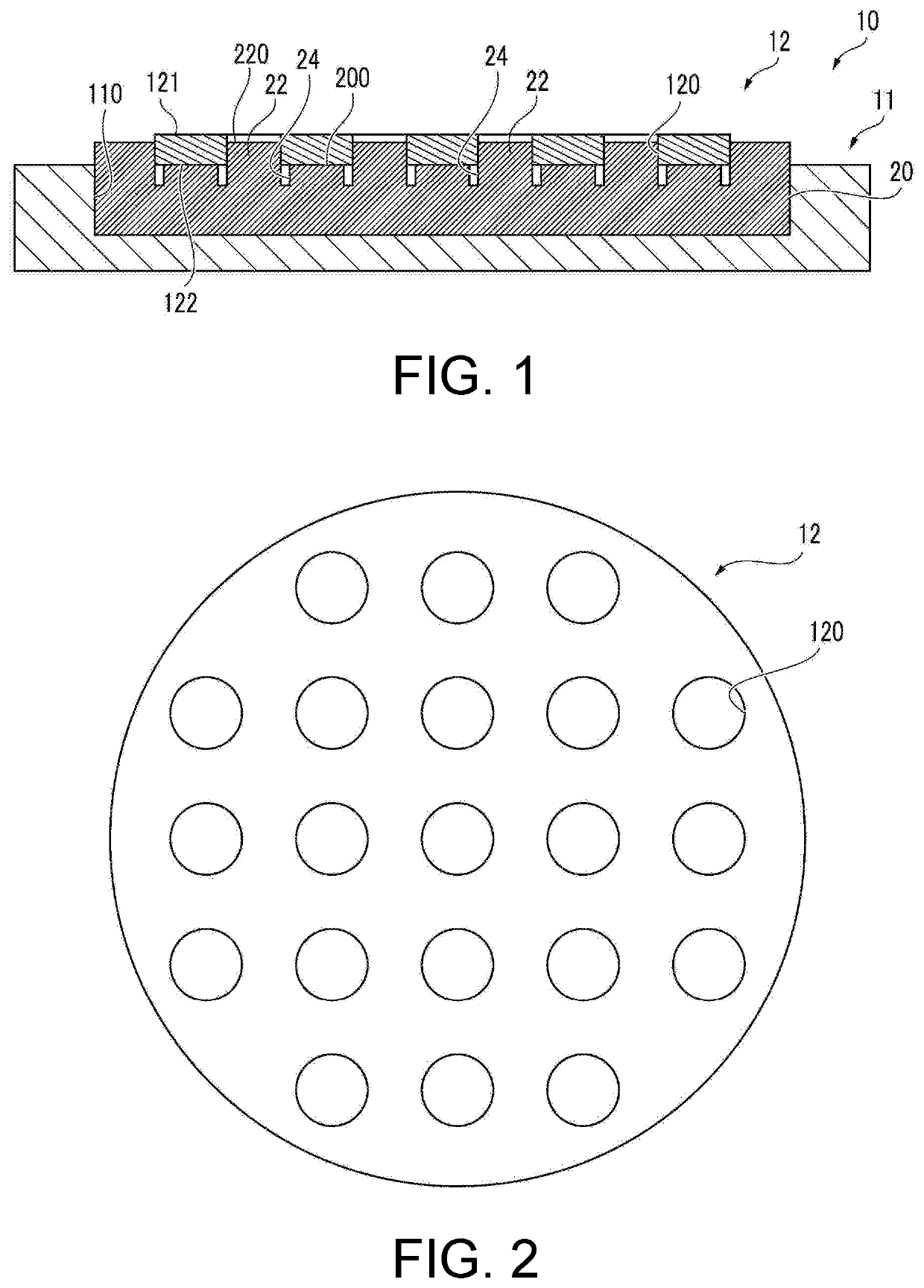
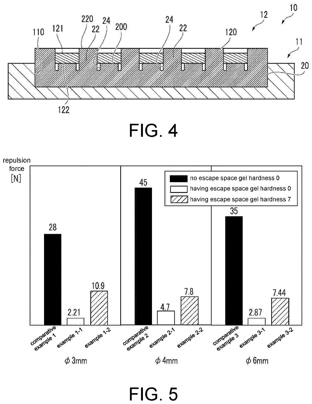
[0020]An artificial epidermis structure used as a first embodiment of the disclosure shown in FIG. 1 includes a container with lid 10 and a gel substance 20 accommodated in the container with lid 10. FIG. 1 is a schematic diagram, and an aspect ratio or the like of each of the container with lid 10, the gel substance 20, and each component thereof is different from an actual artificial epidermis structure (the same also applies to FIG. 2 and the following diagrams).

[0021]The container with lid 10 includes a container 11 and a lid member 12. The container 11 is configured by a substantially disc-shaped synthetic resin for example, and has a concave portion 110 in which a central portion is concave in a substantially cylindrical shape from an upper end surface of the container 11. In the lid member 12, a plurality of holes 120 is formed. The plurality of holes 120 has a diameter slightly smaller than that of the concave portion 110 of the container 10, is configur...

example 1-2

[0030]The artificial epidermis structure of Example 1-2 having the same configuration as Example 1-1 except that a polyurethane gel having an ASKER C hardness of “7” is prepared as the gel substance 20 is manufactured.

example 2-1

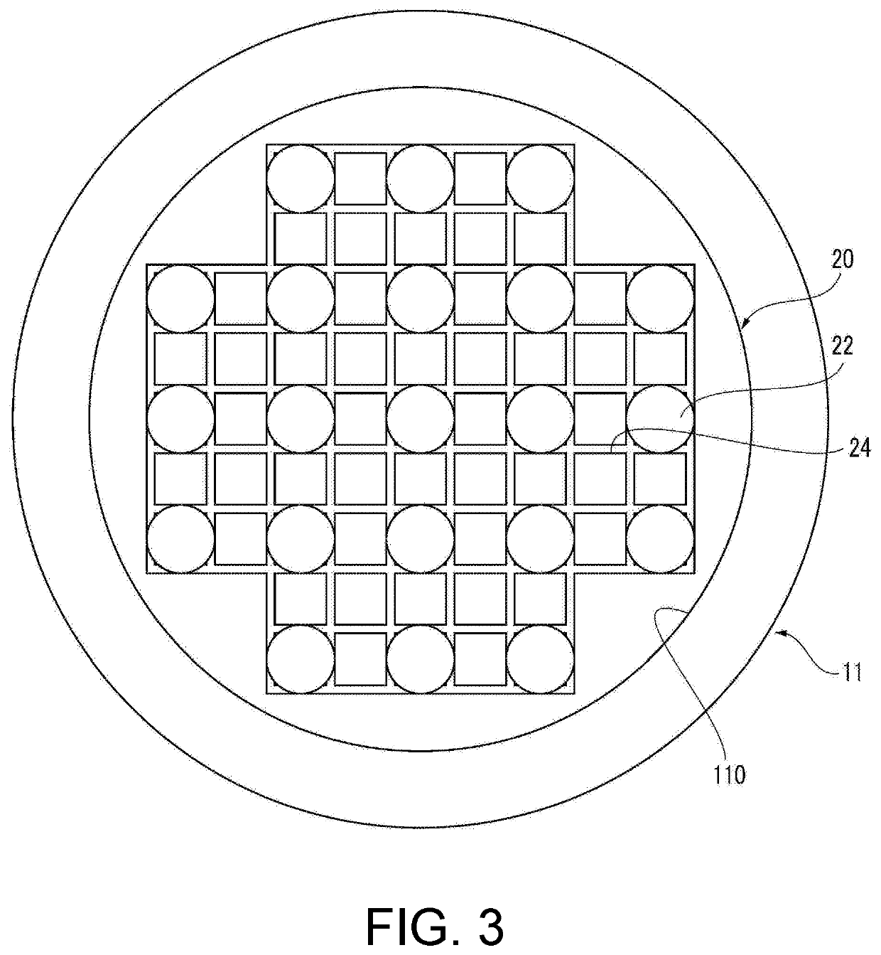
[0031]A substantially disc-shaped lid member 12 having a diameter ϕ of 4 mm and a thickness t of 2.5 is prepared, and a total of 21 (=1×3+3×5+1×3) holes 120 having a diameter ϕ of 4 mm and disposed to form lattice points of a substantially square lattice are formed in the lid member 12 (see FIG. 2). On the front surface 200 of the gel substance 20, a total of 21 substantially frusto-conical convex portions 22 disposed to form lattice points of a square lattice and the concave portions 24 are formed, the convex portions 22 having a substantially trapezoidal cross section in which the lower width is 4 mm, the upper width is 3.302 mm, and the height is 3.5 mm, the concave portions 24 extending vertically and horizontally around each convex portion 22 (see FIG. 3). The volume of the space that is formed by the concave portions 24 between the lid member 12 and the gel substance 20 is 2457.982 mm3. The artificial epidermis structure of Example 2-1 having the same configuration as Example ...


PUM


Abstract

An artificial epidermis structure capable of using a gel substance to adjust a frictional property with high precision is provided. When a front surface of a lid member comes into contact with a target object and pressure acts on the lid member, a part of the gel substance can escape into a space that is formed by concave portions on a front surface of a gel substance. Therefore, reduction in a repulsion force of the gel substance is achieved. Accordingly, the pressure can be appropriately transmitted to the gel substance via the lid member, and convex portions of the gel substance can be caused to easily bulge out over the front surface of the lid member via holes of the lid member.

Description

CROSS-REFERENCE TO RELATED APPLICATION[0001]This application claims the priority benefit of Japan Application No. 2019-030437, filed on Feb. 22, 2019. The entirety of the above-mentioned patent application is hereby incorporated by reference herein and made a part of this specification.BACKGROUND OF THE DISCLOSURETechnical Field[0002]The disclosure relates to an artificial epidermis structure used as an epidermis of a robot hand or the like.Related Art[0003]An artificial epidermis structure (artificial skin) is proposed which has a frictional property close to the frictional property of human skin and in which a weak frictional force can be applied to a target object when pressure received from the target object is small while a strong frictional force can be applied to the target object when the pressure is large (for example, see patent literature 1).[0004]As the artificial epidermis structure in which the frictional property changes corresponding to pressure received from the tar...

Claims


Application Information

Patent Timeline
Patent Type & Authority Applications(United States)
IPC IPC(8): B25J15/00
CPCB25J15/0023B25J15/0038A61F2/105B25J19/00B25J15/00A61F2/583
Inventor ISHIZAKI, RYUSUKE
Owner HONDA MOTOR CO LTD
Learn More