
Elastic wiring and method for producing elastic wiring

a technology of elastic wiring and elastic wire, which is applied in the direction of extensible conductor cables, medical science, diagnostics, etc., can solve the problems of affecting the service life of the cable, the signal-to-noise ratio (s/n ratio) tends to deteriorate, and the long length of the cable has slackness, etc., to achieve excellent waterproofness and elasticity, and the effect of negligible discomfort when worn

Pending Publication Date: 2020-08-27
NIPPON TELEGRAPH & TELEPHONE CORP
View PDF0 Cites 0 Cited by
  • Summary
  • Abstract
  • Description
  • Claims
  • Application Information

AI Technical Summary

Benefits of technology

The present invention is an elastic wiring that has excellent waterproofness and elasticity. It can be applied to clothing without compromising the fabric's elasticity or causing discomfort when worn.

Problems solved by technology

When the wiring is placed in an unstable state at a position away from the body, noise due to body movement or wiring vibration is picked up and the signal-to-noise ratio (S / N ratio) tends to deteriorate.
The wiring, due to generally lacking elasticity and being relatively rigid, is producing with a long length having slack, with the remainder of the wiring often being bundled and fixed to the body at multiple locations using adhesive tape or the like.
However, since the wiring is rigid, a sense of discomfort is likely to arise at the time of wearing.
In particular, wiring of a medical standard is often heavy and hard due to demands such as withstanding voltage, tensile strength, and suppression of impedance fluctuations, and so such wiring is likely to be subject to vibration and impart a great sense of discomfort when touching the skin.
However, since the wiring has poor elasticity and is rigid, the elasticity of the fabric is impaired at the portion where the wiring is attached, and the comfort becomes worse.
However, a sufficient effect is often not obtained, with the decrease in productivity and workability that results from such measures being a problem.
Also, with wearable biological signal acquisition devices, measurement of biological signals such as electrocardiograms and electromyograms becomes difficult if the wiring gets wet due to swimming, bathing, sweating, rain, or the like.

Method used


Image

  • Elastic wiring and method for producing elastic wiring
  • Elastic wiring and method for producing elastic wiring
  • Elastic wiring and method for producing elastic wiring

Examples


Embodiment Construction

[0029]Hereinafter, an example of the elastic wiring according to the present invention will be described. The dimensions of the drawings illustrated in the following description are merely examples, with the present invention not necessarily being limited thereto and may be appropriately changed within a range that does not alter the gist of the present invention.

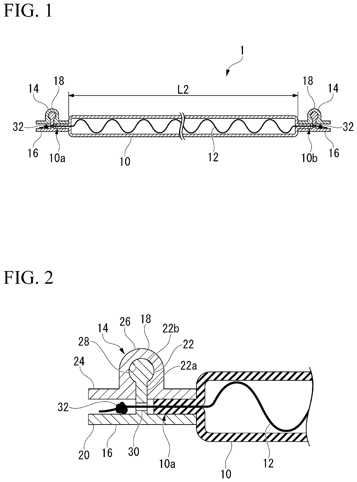
[0030]An elastic wiring 1 according to the present embodiment is provided with a tube 10, a conductor wire 12, and a caulking member 14 as shown in FIG. 1.

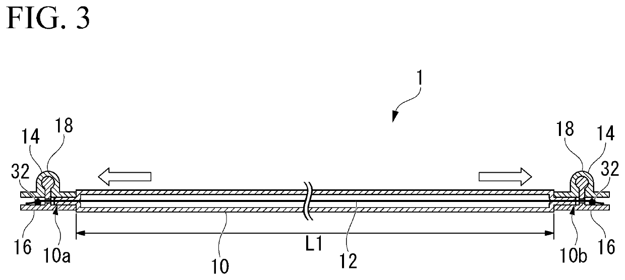
[0031]The conductor wire 12 is arranged within the tube 10 so as to extend from a first end portion 10a to a second end portion 10b in the lengthwise direction of the tube 10. In the elastic wiring 1, the conductor wire 12 and the tube 10 are fixed by caulking by the caulking member 14 at both ends of the tube 10 in the lengthwise direction, namely, the first end portion 10a side and the second end portion 10b side.

[0032]The tube 10 has elasticity. That is, the tube 10 is...


PUM

PropertyMeasurementUnit
outer diameteraaaaaaaaaa
thicknessaaaaaaaaaa

Abstract

An elastic wiring includes: an elastic tube; a conductor wire arranged within the tube; and fixing portions that fix the conductor wire and the tube at both ends of the tube in the lengthwise direction, wherein the length of the conductor wire between the fixing portions when the tube is in an unextended state is longer than the length of the tube between the fixing portions.

Description

TECHNICAL FIELD[0001]The present invention relates to an elastic wiring and a method for producing an elastic wiring.[0002]Priority is claimed on Japanese Patent Application No. 2017-220478, filed Nov. 15, 2017, the content of which is incorporated herein by reference.BACKGROUND ART[0003]In for example a medical device, a health device, a physiological function testing device, or a research device that acquires an electrical biological signal such as an electrocardiograph or an electroencephalograph, the electrical signal is transmitted and received between a bioelectrode in contact with the living body and the device. For that reason, the bioelectrode and the device are connected by wiring (for example, Non-Patent Documents 1 and 2). When the wiring is placed in an unstable state at a position away from the body, noise due to body movement or wiring vibration is picked up and the signal-to-noise ratio (S / N ratio) tends to deteriorate. On the other hand, a body has a large capacitan...

Claims


Application Information

Patent Timeline
Patent Type & Authority Applications(United States)
IPC IPC(8): H01B7/06H02G1/08A61B5/024A61B5/00A41D1/00
CPCH02G1/08A61B5/6804A41D1/005A61B5/02438H01B7/06A61B5/25A61B5/291H01B7/04H01B7/282
Inventor TSUKADA, SHINGONAKASHIMA, HIROSHI
Owner NIPPON TELEGRAPH & TELEPHONE CORP
Learn More