Power control unit

a power control unit and power supply technology, applied in the direction of control/drive circuits, supports/enclosements/casings, dynamo-electric machines, etc., can solve the problems of direct visual confirmation of maintenance and degrading workability, and achieve the effect of improving the workability of the connection conductor in the internal power feeding passage , the effect of removing the connection conductor

a power control unit and power supply technology, applied in the direction of control/drive circuits, supports/enclosements/casings, dynamo-electric machines, etc., can solve the problems of direct visual confirmation of maintenance and degrading workability, and achieve the effect of improving the workability of the connection conductor in the internal power feeding passage , the effect of removing the connection conductor

US20200274424A1Active Publication Date: 2020-08-27HONDA MOTOR CO LTD

Image

  • Power control unit
  • Power control unit
  • Power control unit

Examples


Embodiment Construction

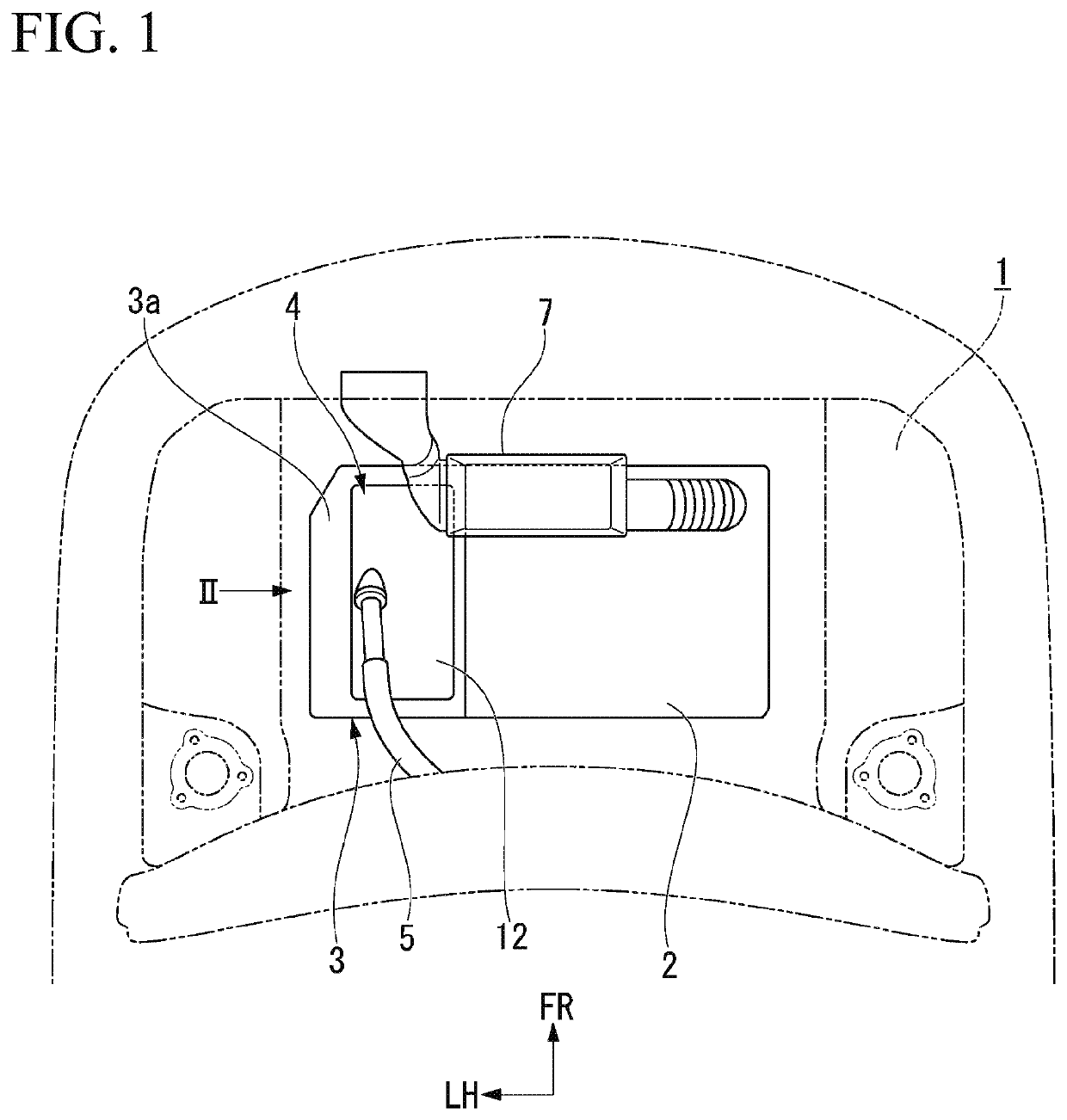
[0031]Hereinafter, an embodiment of the present invention will be described with reference to the accompanying drawings. Further, in some of the drawings, an arrow FR indicates a forward direction with respect to a vehicle, an arrow UP indicates an upward direction with respect to the vehicle, and an arrow LH indicates a leftward direction with respect to the vehicle.

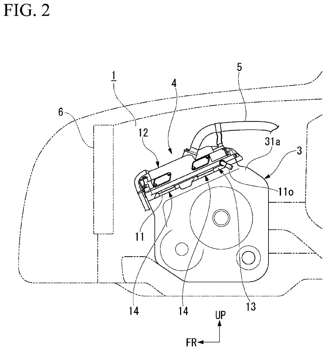
[0032]FIG. 1 is a view showing an engine compartment 1 of a vehicle from above, and FIG. 2 is a schematic side view corresponding to an arrow II in FIG. 1.

[0033]An engine 2 and a motor unit 3 that are configured to drive the vehicle are mounted in the engine compartment 1 of the vehicle. The motor unit 3 performs driving of the vehicle and regenerative power generation according to traveling circumstances of the vehicle. The motor unit 3 is integrally coupled to a side portion of the engine 2. A power control unit 4 configured to convert electric power of a high voltage battery (not shown) into an alternating current an...


PUM


Abstract

A power control unit includes a power module, a support block configured to support the power module, an upper case configured to cover the power module from above, and a connection conductor configured to connect an internal power feeding passage on the side of the power module and an external power feeding passage on the side of the motor unit, wherein the connection conductor vertically passes through the support block and includes a connecting fixing section that protrudes upward than the support block and that is connected to the internal power feeding passage by a fastening member, an inclination wall inclined downward toward a side end portion of the upper wall of the upper case is provided on the upper wall of the upper case, and an opening section facing the connecting fixing section of the connection conductor is provided in the inclination wall.

Description

CROSS-REFERENCE TO RELATED APPLICATION[0001]Priority is claimed on Japanese Patent Application No. 2019-033239, filed Feb. 26, 2019, the content of which is incorporated herein by reference.BACKGROUND OF THE INVENTIONField of the Invention[0002]The present invention relates to a power control unit disposed on an upper section of a motor unit.Description of Related Art[0003]A configuration in which a power control unit is connected to an upper section of a motor unit mounted in a vehicle is known. A power module including a function of an inverter, a boosting converter, or the like, configured to drive a motor and perform regeneration is installed in the power control unit. A power feed connecting module configured to connect power feeding passages of three phases on the side of the motor unit and power feeding passages of three phases on the side of the power module is provided between the motor unit and the power control unit (for example, see Japanese Unexamined Patent Application...

Claims


Application Information

Patent Timeline
27 Aug 2020
Publication
US20200274424A1
IPC
H02K11/33; H02K5/22
CPC
H02K11/33; H02K5/225; H02K11/30; H02K5/203
Inventors
KUNII, HIROSHI; HAYASHI, AKINARI