
Method for calibrating a characteristic diagram ofa work machine and work machine

a characteristic diagram and work machine technology, applied in mechanical equipment, transportation and packaging, brake systems, etc., can solve problems such as changes with the duration of the service life of the working machin

Inactive Publication Date: 2020-09-03
ZF FRIEDRICHSHAFEN AG
View PDF0 Cites 0 Cited by
  • Summary
  • Abstract
  • Description
  • Claims
  • Application Information

AI Technical Summary

Benefits of technology

The patent is about a method to optimize the behavior of a drive input clutch in a working machine. This method can prevent damage to the machine by ensuring that it operates within its power limit. The control unit of the machine has a characteristic diagram that is tailor-made for the machine and can be adjusted as needed to improve its efficiency. Additionally, if there are any signs of wear or higher fuel consumption, the machine's efficiency can be brought back to its calibration condition by correcting the characteristic diagram virtually automatically. Overall, this method helps to prolong the lifespan and optimize the performance of the working machine.

Problems solved by technology

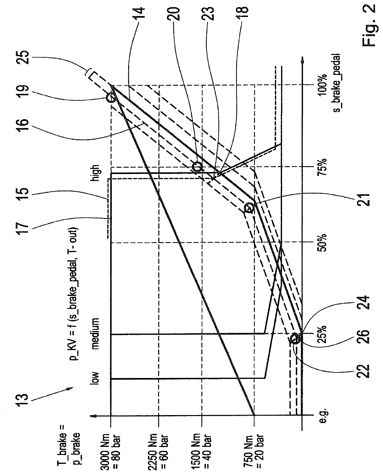
The nominal relationship or the relationship of the nominal brake pedal characteristic to the nominal clutch characteristic represents an ideal behavior of the system which, however, changes with the duration of the working machine's service, in particular due to wear.

Method used


Image

  • Method for calibrating a characteristic diagram ofa work machine and work machine
  • Method for calibrating a characteristic diagram ofa work machine and work machine

Examples


Embodiment Construction

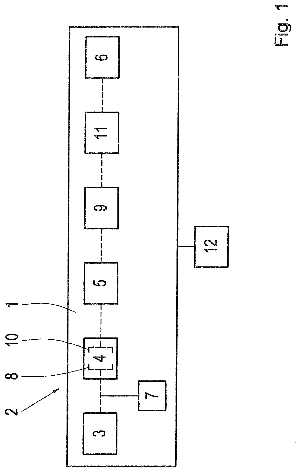
[0027]FIG. 1 shows a drive-train 1 of a working machine 2. The drive-train 1 comprises a drive unit 3, which drives one or more consumers by way of a hydrodynamic torque converter 4 and a drive input clutch 5. The working machine 1 drives wheels 6 and at least one power take-off 7 such as hydraulic pumps for actuating loading scoops.

[0028]The torque converter 4 is on the one hand functionally connected to the drive unit 3 so that torque of the drive unit 3 can be transmitted to an impeller 8 of the torque converter 4. On the other hand, on the wheel side the torque converter 4 is connected to the drive input clutch 5 and / or to a transmission 9. A turbine wheel 10 of the hydrodynamic torque converter 4 receives the flow energy produced by the impeller 8 and supplies it in the form of mechanical energy to the drive input clutch 5 and the transmission 9, whereby preferably at least one wheel 6 is driven.

[0029]On the drive input side, the power take-off 7 is connected upstream from the ...


PUM


Abstract

A method is described for calibrating a characteristic diagram of a working machine. The characteristic diagram includes a brake pedal characteristic of a brake system and at least one clutch characteristic of a drive input clutch which, in the calibrated condition, have a nominal relationship to one another. The method having the steps of: determining a wheel-side drive output torque; determining an actual brake pedal characteristic with reference to the drive output torque; determining an actual relationship that differs from the nominal relationship by comparing the actual brake pedal characteristic with a nominal brake pedal characteristic; and calibrating the brake pedal characteristic or the clutch characteristic in such manner that the actual relationship corresponds to the nominal relationship. In addition a working machine with a control unit for carrying out the method is described.

Description

[0001]This application is a National Stage completion of PCT / EP2018 / 078331 filed Oct. 17, 2018, which claims priority from German patent application serial no. 10 2017 220 485.0 filed Nov. 16, 2017.FIELD OF THE INVENTION[0002]The present invention relates to a method for calibrating a characteristic diagram of a working machine and to a working machine with an electronic control unit for carrying out the method.BACKGROUND OF THE INVENTION[0003]From automotive technology, working machines such as forklift trucks, wheel loaders or other special vehicles are known, which are equipped with a hydrodynamic drive unit. The hydrodynamic drive unit usually consists of a drive motor, a hydrodynamic torque converter and a transmission downstream therefrom. In the known working machines it is usual for low travel speeds to be required when picking up certain loads, but in that driving condition the working hydraulic system needs maximum power in order to take up the loads or to carry out other ...

Claims


Application Information

Patent Timeline
Patent Type & Authority Applications(United States)
IPC IPC(8): B60W50/06F16H63/40F16H61/02B60W10/02B60W10/18B60W10/10B60W30/18
CPCB60W10/024B60W50/06B60W2050/0088B60W2510/02B60W10/10B60W2520/30B60W10/18B60W30/18109B60W2540/12F16H63/40B60W2300/15B60W2050/0026F16H61/0213B60T7/042B60T13/662B60W10/02B60W10/06B60W30/18027B60W50/00B60W2710/0644B60W2710/1005F16D48/06F16D2500/30806F16D2500/3108F16D2500/3117F16D2500/31426F16D2500/70434F16D2500/70454F16D2500/70488F16D2500/7049F16D2500/70605
Inventor HÖFLER, HANSBREHMER, UDOKURZ, THOMAS
Owner ZF FRIEDRICHSHAFEN AG
Learn More