
Bone model, modelling process and system therefor

a modeling process and bone technology, applied in the field of orthopaedic surgical planning and implant design, can solve the problems of increased sensitivity, bone failure, implant-bone interface failure as well as implant failure,

Pending Publication Date: 2020-09-10
VERSITECH LTD
View PDF1 Cites 6 Cited by
  • Summary
  • Abstract
  • Description
  • Claims
  • Application Information

AI Technical Summary

Benefits of technology

The present invention provides a model and system that has several advantages over the prior art. Specifically, it addresses the issue of incomplete or inaccurate data in a more efficient and effective way. This can lead to better performance and improved reliability in various applications. Overall, this innovation offers a better solution for managing data and making it easier to use.

Problems solved by technology

Orthopaedic implants, including fixation implants and prosthetic implants, are implanted within bone of a subject, and a bone-implant system must be able to withstand large stresses from typical and non-typical loading, and such loading may cause bone failure, implant-bone interface failure as well as implant failure.
In respect of aging population subjects, assessment of structural integrity of bone may be required for surgical planning and implant design, due to loss in quality of bone stock, osteoporosis and degenerative bone disease.
Subjects having such compromised bone stock, in addition to increased susceptibility to trauma and fracture, may have limitations to types of implants, and increased sensitivity to exacerbated stress, giving rise to likelihood of further complications and fracture, as well as aseptic loosening.
A common complication and mode of failure of a fixation implant in osteoporotic patients is “cut-out”, whereby the end or tip of an implant pushes through the trabecular bone and into surrounding tissues, such as the adjacent joint cartilage or bone due to physiological loading.
Corrective, or revision, surgery is generally subsequently required, and due to damage of bone at the surgical site, there may be insufficient or compromised bone stock, causing difficulties and complications during corrective or restorative surgery.
In the case of prosthetic implants, whereby such implants are in contact with and are at least party supported by trabecular bone, subsidence or instability of such an implant may occur due to implant movement within the trabecular bone as well as bone failure.
Aseptic loosening is a common problem associate with such implants, often requiring revision surgery at high cost and risk to the patient.

Method used


Image

  • Bone model, modelling process and system therefor
  • Bone model, modelling process and system therefor
  • Bone model, modelling process and system therefor

Examples


Embodiment Construction

[0074]The present invention relates to a method and system for orthopaedic surgical planning and implant design, and in particular to a method and system for orthopaedic surgical planning and implant design based on anatomic data.

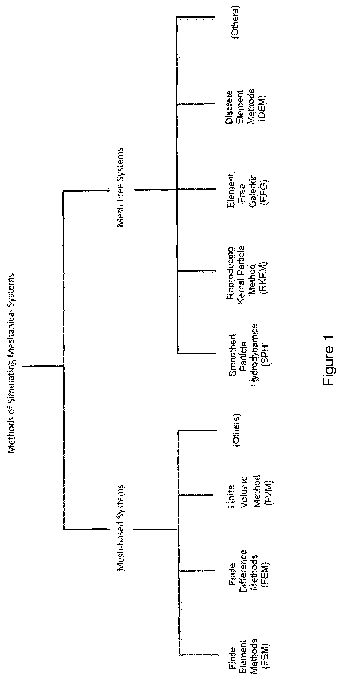
[0075]The present invention provides a system for modeling the mechanical behavior of bone and bone fixation implants and devices for internal fixation of bone which are inserted in trabecular bone.

[0076]The system of the present invention is also applicable for modelling the mechanical behavior of prosthetic implants, in addition to fixation implants, when affixed within bone including trabecular bone.

[0077]Both fixation implants and prosthetic implant are required to be maintained in a requisite location within the bone of a subject, and migration of such implants following surgical implantation is an undesirable effect, leading to clinical complications.

[0078]In the case of fixation implants, migration within bone can cause clinical complications such as...


PUM


Abstract

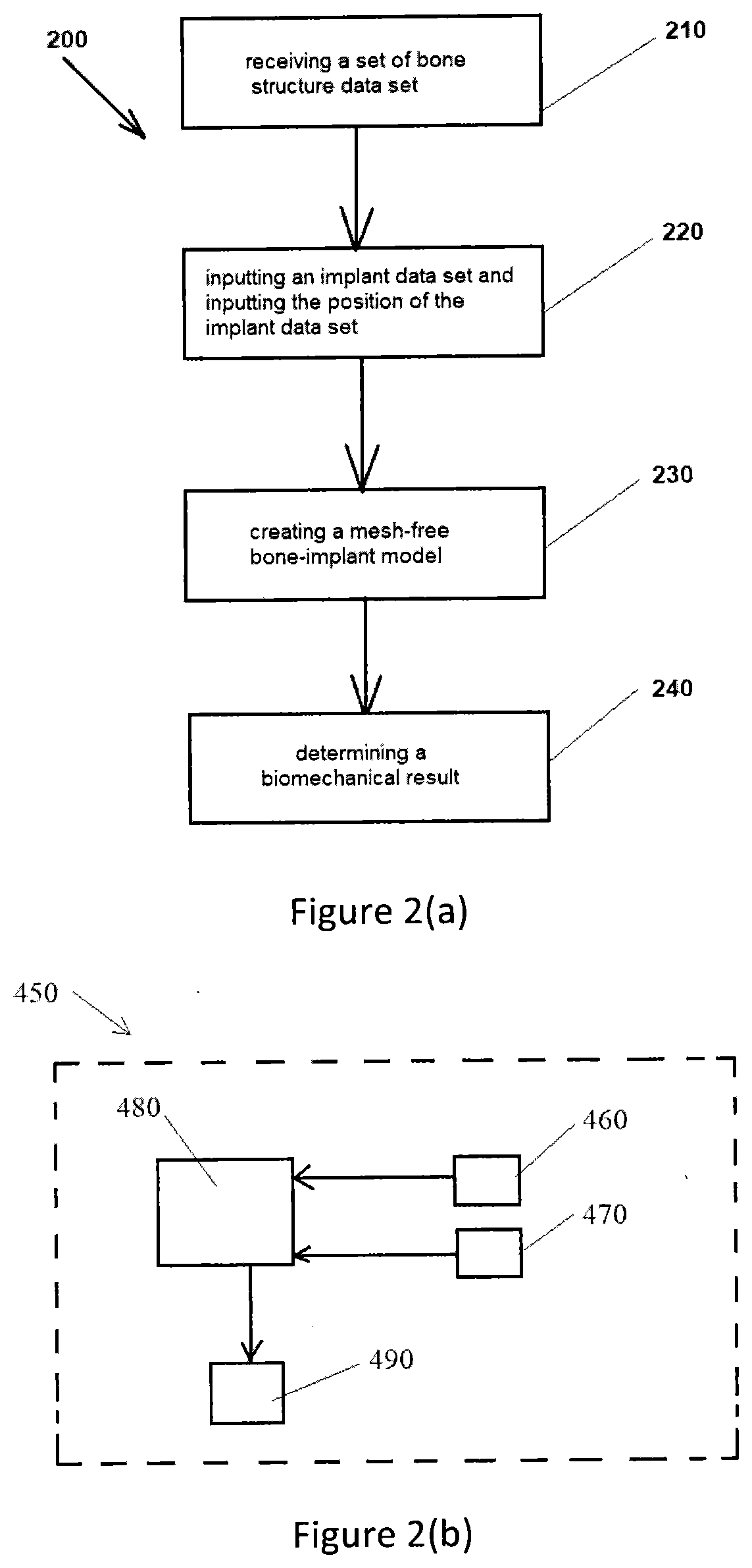
A computer-implemented bone-implant system evaluation method for application of mesh-free analysis of a bone-implant system for evaluation of performance of a bone-implant system for an implant implanted within the bone structure at an anatomical site, said method comprising (i) receiving a set of bone structure data set, wherein set of bone structure data includes data indicative of the bone structure at an anatomical site; (ii) inputting an implant data set and inputting the position of the implant data set, wherein the implant is selected based upon the biomechanical requirements for the anatomical site and the position and of the implant data set is indicative of the position of the implant with respect to the anatomical site, wherein implant data set includes data representative of the geometry and materials properties of the implant; (iii) creating a bone-implant model, wherein said bone implant-model includes a mesh-free model of trabecular bone at the anatomical site wherein the bone-implant model is formed from the bone structure data set from step (i) and the implant data set from step (ii), and wherein the mesh-free model of trabecular bone is indicative of the trabecular bone structure of the bone structure at the anatomical site; and (iv) determining a biomechanical result based upon computer simulated loading of the bone-implant system based upon mesh-free analysis of the bone-implant model, wherein the biomechanical result includes data based on the displacement of the implant relative to the bone of bone-implant model.

Description

TECHNICAL FIELD[0001]The present invention relates to a method and system for orthopaedic surgical planning and implant design, and in particular to method and system for orthopaedic surgical planning and implant design based on anatomic data.BACKGROUND OF THE INVENTION[0002]The long-term integrity and stability of a bone-implant system, such as trauma fixation, corrective surgery, joint replacement or restoration and the like, is paramount for success of clinical outcomes in surgical applications.[0003]Orthopaedic implants, including fixation implants and prosthetic implants, are implanted within bone of a subject, and a bone-implant system must be able to withstand large stresses from typical and non-typical loading, and such loading may cause bone failure, implant-bone interface failure as well as implant failure.[0004]Biomechanical analysis of a bone-implant system can be performed during the design process of an implant by way of biomechanical analysis of bone-implant systems. ...

Claims


Application Information

Patent Timeline
Patent Type & Authority Applications(United States)
IPC IPC(8): A61F2/30G06F30/20G16H50/70G16H10/60G16H30/40
CPCA61F2002/30948G16H50/70G16H30/40G16H10/60A61F2002/30952A61F2/30942G06F30/20A61B34/10A61B2034/108A61B2034/105
Inventor KULPER, SLOAN AUSTINNGAN, HING WAN ALFONSOFANG, XINSHUO CHRISTIANGUO, MARGARETLU, WEIJIA WILLIAMLEUNG, KA LI FRANKIE
Owner VERSITECH LTD
Learn More