Supercharge Your Innovation With Domain-Expert AI Agents!

Automotive laminate with superior camera window

a technology of laminated glass and superiority, applied in the direction of layered products, transportation and packaging, chemical instruments and processes, etc., can solve the problems of annealed glass breaking into large shards with sharp edges, affecting the optical performance of laminated construction, so as to improve the strength and improve the strength of laminated

Active Publication Date: 2020-09-10
AGP AMERICA
View PDF0 Cites 3 Cited by
  • Summary
  • Abstract
  • Description
  • Claims
  • Application Information

AI Technical Summary

Benefits of technology

This invention is about a type of glazing for cars that has a space inside the glass where cameras can be placed. The cameras can be attached to the outside of the glass or directly to the glass. The space between the camera and the edge of the glass can be filled with a strong adhesive to make it even stronger. The part that attaches to the camera can go all the way to the edge of the glass to make it even stronger. The windscreen can also have a special lens to correct any optical problems. This invention has several advantages: it provides better quality optics, corrects for the shape of the glass, reduces double images, compensates for installation angle, and improves safety. It is made using standard automotive glass processes.

Problems solved by technology

At the same time, windshields, where many of the cameras are mounted, are becoming larger and more complex in shape.
Annealed glass breaks into large shards with sharp edges.
This laminated construction presents problems in the area of optics, as shown in FIGS. 1, 2A and 2B.
The curvature of the glass, in conjunction with the often low installation angle, can also contribute to double image as well as further reducing the optical clarity of the field of view.

Method used


Image

  • Automotive laminate with superior camera window
  • Automotive laminate with superior camera window
  • Automotive laminate with superior camera window

Examples


Embodiment Construction

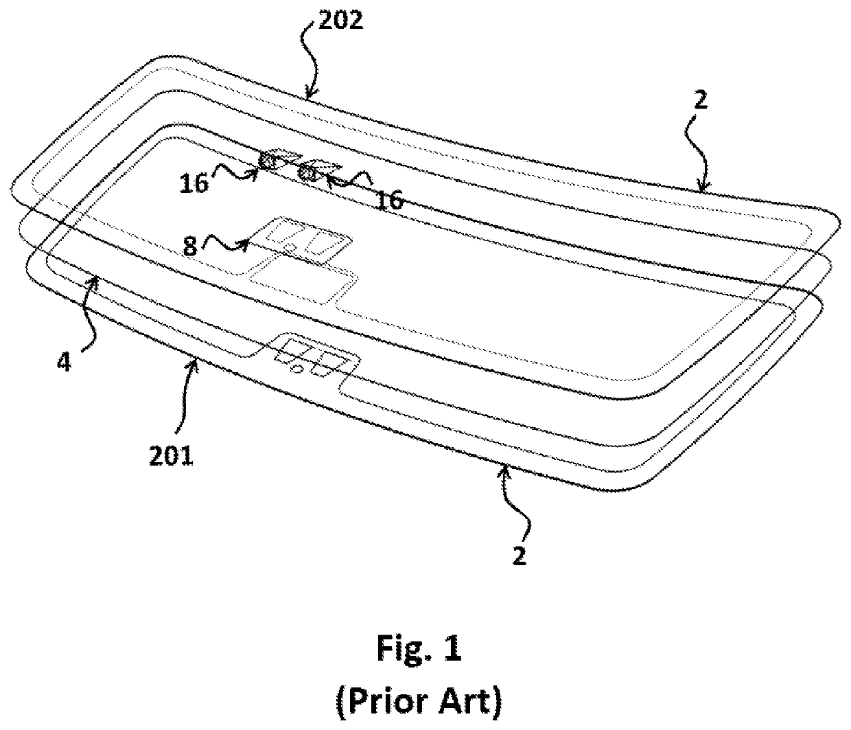
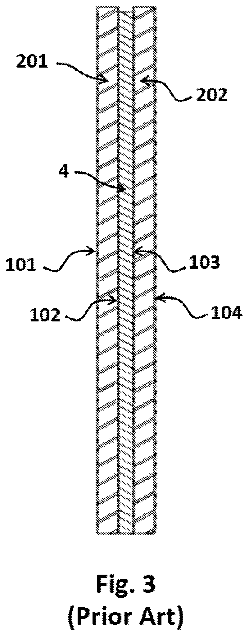
[0062]In the drawings and discussion, the following terminology is used to describe the configuration of a laminated glazing. A typical automotive laminate, as shown in FIG. 3, is comprised of two layers of glass, the exterior or outer 201 and interior or inner 202 that are permanently bonded together by a plastic layer 4 (interlayer). The glass surface that is on the exterior of the vehicle is referred to as surface one 101 or the number one surface. The opposite face of the exterior glass layer 201 is surface two 102 or the number two surface. The glass surface that is on the interior of the vehicle is referred to as surface four 104 or the number four surface. The opposite face of the interior layer of glass 202 is surface three 103 or the number three surface. Surfaces two 102 and three 103 are bonded together by the plastic layer 4.

[0063]The plastic bonding layer 4 has the primary function of bonding the major faces of adjacent layers to each other. The material selected is typ...


PUM

PropertyMeasurementUnit
thicknessesaaaaaaaaaa
radiusaaaaaaaaaa

Abstract

The use of camera based safety systems is growing at a rapid rate in modern automobiles. As the industry moves for full autonomous capability, the number of cameras required is increasing. At the same time, windshields, where many of the cameras are mounted are 5 becoming larger and more complex in shape. This presents problems in the area of camera optics. For one, the camera is looking out through at least two layers of bent glass bonded together by a third layer of plastic. Mismatches in the refractive index can result in a double image. The curvature of the glass turns the window into a lens and, in conjunction with the often low installation angle, can reduce the optical clarity of the camera field of view. The 0 laminate of the invention has a cutout in the area of the camera(s) on the interior glass layer where the cameras are mounted. The cameras are mounted directly to the glass via a bracket or adhesive or to a thin transparent insert. The glass can also be fitted with a lens system optically bonded to the glass for even better performance. The result is a laminated glazing with superior optical quality.

Description

FIELD OF THE INVENTION[0001]The present invention is related to a laminated automotive glazing.BACKGROUND OF THE INVENTION[0002]The use of cameras based safety systems, requiring a wide field of view and a high level of optical clarity, is growing at a rapid rate. As the industry moves towards full autonomous capability, the number of cameras and resolution is increasing. At the same time, windshields, where many of the cameras are mounted, are becoming larger and more complex in shape.[0003]The main cameras require a high, forward looking field of view and so must typically be mounted on the windshield and in the wiper area. Early initial applications were for night-vision. Today, camera based systems are used to provide a wide array of safety functions including adaptive cruise control, obstacle detection, lane departure warning and support for autonomous operation. Many of these applications require the use of multiple cameras. A clear undistorted field of view, with minimal doub...

Claims


Application Information

Patent Timeline
Patent Type & Authority Applications(United States)
IPC IPC(8): B60R11/04B32B17/10
CPCB32B17/10036B60R11/04B32B17/10293B32B17/10761
Inventor MANNHEIM ASTETE, MARIO ARTUROVOELTZEL, CHARLES STEPHENSUAREZ, JUAN PABLOGORDON, PHILIP DENTONSARMIENTO SANTOS, ANDRES FERNANDO
Owner AGP AMERICA
Features
  • R&D
  • Intellectual Property
  • Life Sciences
  • Materials
  • Tech Scout
  • Unparalleled Data Quality
  • Higher Quality Content
  • 60% Fewer Hallucinations
Learn More