Method and device for optically examining a plurality of microscopic samples

a technology of optical examination and microscopic samples, applied in the field of optical examination, can solve the problems of inability to collect two- or three-dimensional image information, general non-operational imaging, and inability to carry out imaging, so as to achieve the effect of increasing process efficiency and substantially increasing outpu

Active Publication Date: 2020-09-10
CARL ZEISS MICROSCOPY GMBH
View PDF0 Cites 3 Cited by
  • Summary
  • Abstract
  • Description
  • Claims
  • Application Information

AI Technical Summary

Benefits of technology

[0020]The non-zero angle allows the use of a detection optical unit, as is usually used in light sheet microscopy, and the positioning thereof in such a way that the focal plane lies in the intersection region, ideally directly in the light sheet plane or at least parallel thereto such that the whole—oblique—cross section of the flow channel lies in the intersection region in the focal plane. Since the entire cross section of the flow channel is captured, use can also be made of relatively large channels, i.e., the channel size can be chosen independently of the sample size. This facilitates the recording of snapshots of the sectional images of the samples typical for light sheet microscopy in the intersection region, i.e., two-dimensional images of the samples passing through the intersection region. In addition to covering a large or even the entire oblique cross section of the flow channel, an oblique alignment of the light sheet relative to the flow direction in microfluidics advantageously allows the use of objectives with a high numerical aperture and short working distances. The detection optical unit can be used not only for the generation of images, but also for the registration of the fluorescence signals for the quantitative analysis, as are carried out in flow cytometric examinations; then, additional detection devices are not required. The imaging detection optical unit thus not only registers the fluorescence signals but simultaneously also images the sample, passing through the intersection region in the focal plane, onto a corresponding area sensor, at least in a snapshot, and so at least one two-dimensional recording of the sample can be generated as said sample passes through the intersection region.
[0023]While imaging in flow cytometry is only possible in the prior art if use is made of an extended depth of field approach (EDOF approach), which necessitates the use of small apertures for imaging, such measures can be dispensed with when using a light sheet microscopy arrangement for illumination and detection purposes: The detection objective is focused on the light sheet plane and the depth of field corresponds to the thickness of the intersection region along the direction of the normal of the light sheet plane and is substantially smaller than the extent of the samples. It is therefore possible to use objectives with a large aperture angle in the detection optical unit, resulting in a high resolution, which grows with the aperture angle of the objective as a matter of principle. The numerical aperture of the objective can be further increased and the resolution can be further increased by using immersion media.
[0026]Since the light sheet can cover a substantially larger area than the diameter of a flow channel for microfluidics, it is readily possible to align the light sheet in such a way that it intersects a multiplicity of flow channels. This allows the throughput to be substantially increased, leading to an increase in the efficiency of the process for flow cytometric and imaging analyses.
[0027]Moreover, the samples can also be illuminated by a plurality of light sheets, the light sheet planes preferably lying parallel with respect to one another. Here, a plurality of similar light sheets can be disposed in succession along the flow direction, facilitating a repeat observation of one and the same object, i.e., the sample separated from the sample batch. A plurality of light sheets with different spectral properties can also be used, for example to observe multi-color excitations. Then, these light sheets can also be overlaid on one another; then, the multi-color excitation takes place simultaneously. Arranging the similar or different light sheets in succession also allows the observation of optical manipulations over time. By way of example, a first light sheet can implement a manipulation that leads to a reaction in the sample. The second light sheet is used to observe a first property and, if necessary, further light sheets can be used to observe further properties, which can also be overlaid. The time that the sample requires to travel the distance between the first and second light sheet can be set by setting the flow speed, for example by way of valves.
[0033]In an apparatus according to the invention, the at least one flow channel is advantageously embodied on an interchangeable channel carrier, for example a microfluidic chip. This facilitates a targeted adaptation to different samples and analysis processes. By way of example, a multiplicity of parallel flow channels that are intersected by the light sheet could be disposed on the channel carrier, i.e., each of the flow channels has an intersection region with a light sheet. This facilitates a higher throughput of samples on account of the parallelization and can be used, in particular, when a multiplicity of samples should be analyzed and the focus is not on an imaging representation; however, the latter can likewise readily be integrated using an area detector: Using the detection optical unit and a camera connected thereto, certain regions on the detector can be uniquely assigned to certain channels on an area detector of the camera so that each of the flow channels can be evaluated separately. If only a quantitative analysis is important, all flow channels on the channel carrier can have a common feed line and a common discharge line. However, the provision of a dedicated feed and / or discharge line for each of the channels or a combination of the channels into groups is also possible, depending on the analyses to be carried out.
[0037]In another configuration, the flow channel is embodied with a changing diameter along the flow direction, facilitating mechanical manipulations of the samples within the meaning of a deformation. The sample is then observed, for example, once before the deformation and once in the deformed state, for the purposes of which two light sheets are used if the flow direction does not change or a single light sheet is used if the at least one flow channel is embodied in such a way that the flow direction changes with respect to a superordinate coordinate system, as is the case in the meandering embodiment of the flow channel.

Problems solved by technology

Only signals are detected in conventional flow cytometry; however, two- or three-dimensional image information, which would be desirable for an even more precise analysis and / or further diversified cataloging, cannot be collected.
Although a high sample throughput can be achieved with these methods, imaging is generally not carried out since focusing cannot be carried out at these speeds.
This disadvantage is at least partly compensated by special image processing.
However, this so-called “extended depth of field” (EDOF) approach increases the technical complexity, and hence the costs, and the achievable resolution in the image is low on account of the small aperture.

Method used


Image

  • Method and device for optically examining a plurality of microscopic samples
  • Method and device for optically examining a plurality of microscopic samples
  • Method and device for optically examining a plurality of microscopic samples

Examples


Embodiment Construction

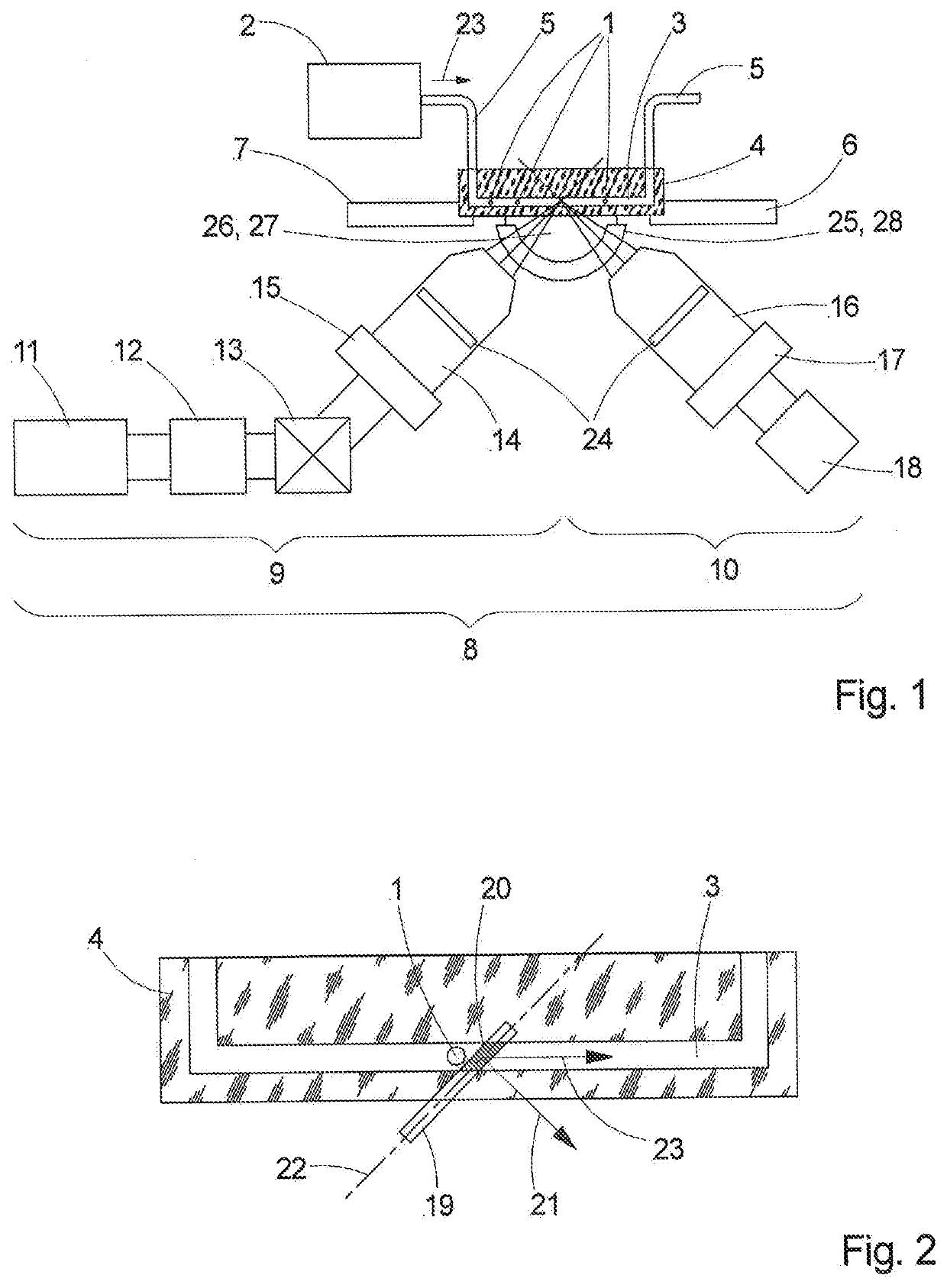
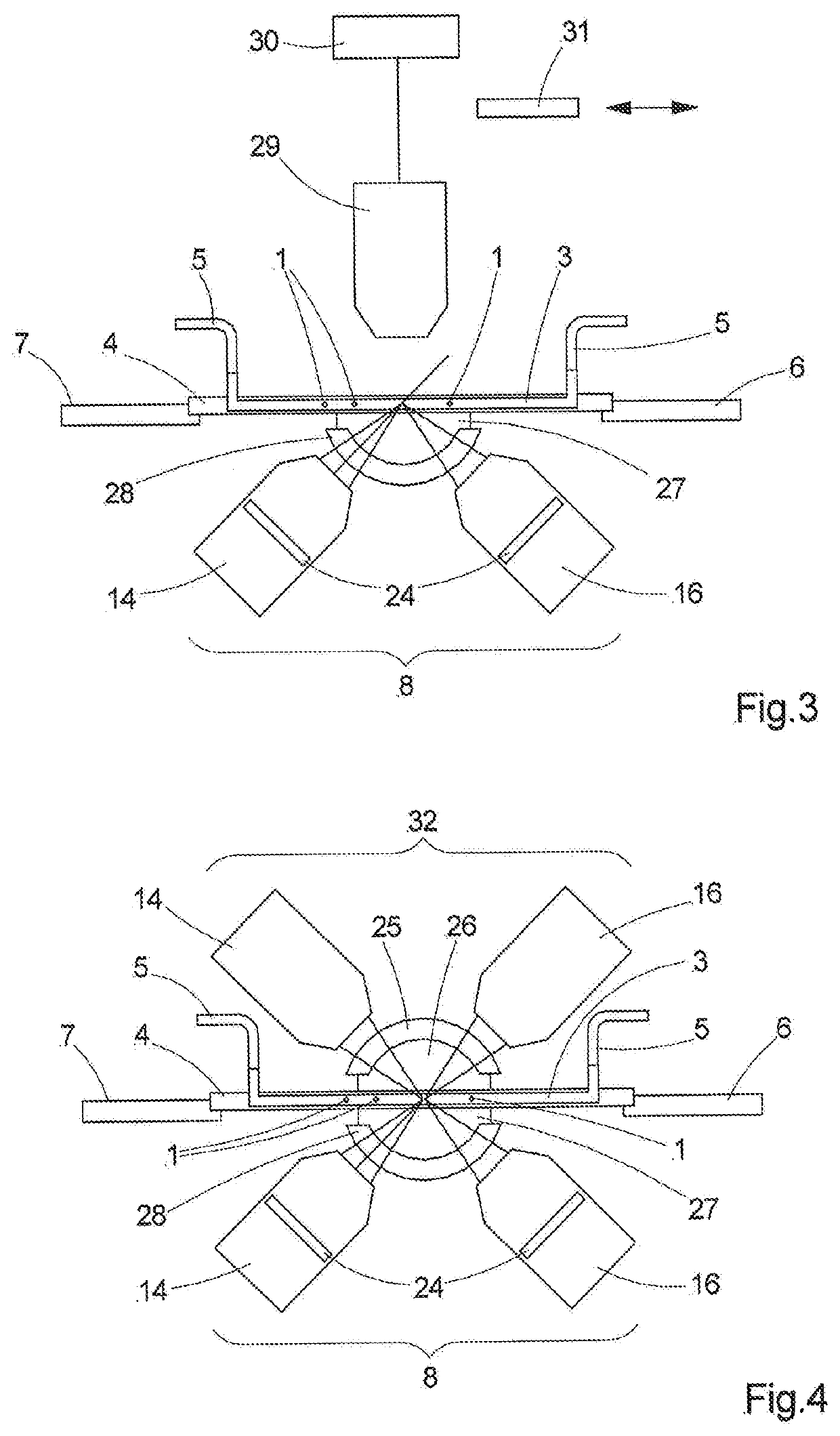
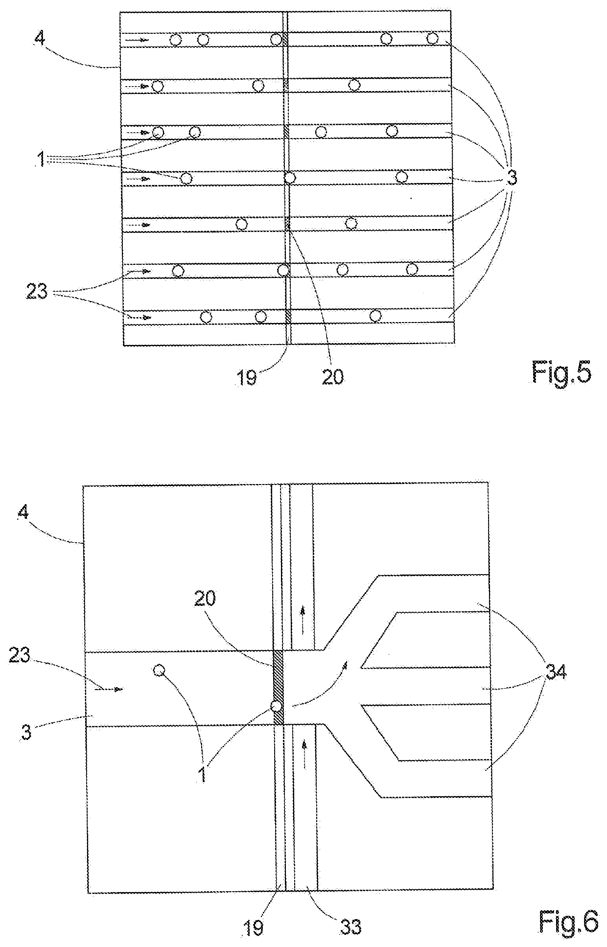
[0014]The object of the invention is to develop a method and an apparatus of the type set forth at the outset, in such a way that, firstly, there is an increase in sensitivity and flexibility in comparison with the flow cytometric methods and apparatuses known in the prior art and, secondly, the most detailed image information is made available at the same time.

[0015]For a method of the type set forth at the outset, this object is achieved by virtue of the samples being illuminated by virtue of at least one light sheet with a light sheet plane being directed on the at least one flow channel and the light sheet being aligned so that it intersects the at least one flow channel in an intersection region and the normal of the light sheet plane includes a non-zero angle with the flow direction in the intersection region. The light emitted from the samples is registered by an imaging detection optical unit, i.e., a detection optical unit that images and detects over an area, the focal pla...


PUM

PropertyMeasurementUnit
diameteraaaaaaaaaa
angleaaaaaaaaaa
thicknessaaaaaaaaaa

Abstract

A method for optically examining a plurality of microscopic samples. The samples are channeled one after the other by means of a flow into at least one flow channel in which the samples advance along a flow direction. The samples are illuminated, and light emitted from the samples is detected and analyzed. A device for carrying out the method in which samples are illuminated in that at least one light sheet with a light sheet plane is directed onto the at least one flow channel, wherein the light sheet is oriented so as to intersect the at least one flow channel in an intersection region, and the normal of the light sheet plane forms an angle differing from null together with the flow direction in the intersection region. The light emitted from the sample is registered by an imaging optical detection unit, and the focal plane of said optical detection unit lies in the intersection region.

Description

RELATED APPLICATIONS[0001]The present application is a U.S. National Stage application of International PCT Application No. PCT / EP2018 / 075949 filed on Sep. 25, 2018, which claims priority benefit of German Application No. DE 10 2017 122 718.0 filed on Sep. 29, 2017, the contents of each are incorporated by reference in their entirety.FIELD OF THE INVENTION[0002]The invention relates to a method for optically examining, more particularly for manipulating, for imaging and for analyzing, a multiplicity of microscopic samples, more particularly biological samples, in which the samples are channeled from the multiplicity thereof and successively guided in at least one flow channel by means of a flow and said samples move therein along a specified flow direction. The samples are illuminated in the flow channel and the light emitted from the samples is detected and analyzed.[0003]The invention also relates to an apparatus for optically examining a multiplicity of microscopic samples, said ...

Claims


Application Information

Patent Timeline
Patent Type & Authority Applications(United States)
IPC IPC(8): G01N15/14G02B21/16G02B21/08
CPCG02B21/082G01N15/147G02B21/16G01N15/1434G01N2015/144G02B21/0032G02B21/0076G02B21/367G01N2015/1006G01N15/1484
Inventor KALKBRENNER, THOMASSIEBENMORGEN, JOERGOHRT, THOMAS
Owner CARL ZEISS MICROSCOPY GMBH
Why Eureka
Try Eureka