Magnetic connector assembly

a technology of magnetically biased connectors and magnetic connectors, applied in the direction of coupling device connection, coupling prevention, engagement/disengagement of coupling parts, etc., can solve the problems of irreparable damage to the connector, the cable or electronic device, and the time-consuming and labor-intensive untangling and proper wire or cable routing

Active Publication Date: 2020-09-10
LEE VINCENT
View PDF0 Cites 9 Cited by
  • Summary
  • Abstract
  • Description
  • Claims
  • Application Information

AI Technical Summary

Benefits of technology

[0012]A Magnetic Connector Assembly has a female connector with spring-loaded conductive pins slightly protruding inside a recess or cavity in the female connector's body. A corresponding male connector has a protrusion on its body with conductive pins slightly indented into the protrusion's surface. The protrusion on the male connector is sized and shaped to fit into the cavity in the female connector such that the male connector's pins engage the pins of the female connector, allowing for electrical communication across the connector assembly. Magnets on the male and female connectors secure them in a correct orientation and alignment.

Problems solved by technology

One problem with prior art connectors that utilize threaded fasteners, for example, or which are not readily connected or disconnected, is that in environments where many cables and connectors are utilized, cable management becomes challenging.
The rigid coupling implements, i.e., threaded fasteners, of known connectors makes untangling and proper wire or cable routing time consuming.
A related problem is that sudden forces on such prior art connectors may cause irreparable damage to the connector, cable or electronic device.
For example, in a hospital environment where electronic devices providing vital patient support functions are connected with prior art “hardline” connectors, medical personnel or others tripping over a cable could result in medical equipment falling and being damaged from impact, abrupt separation from a patient, or other consequences that could be catastrophic to equipment, patients and medical personnel.
Another problem in the prior art is that connectors that utilize multiple pins are prone to damage from misalignment or attempting connection with respective portions in an improper orientation.
Because of their length, the pins are more prone to bending and deformation caused by damage when they are exposed, or by misalignment during the connection process.
If connection is attempted before the connector portions are properly aligned, bending, deformation or other damage may result to one or more pin conductors, rendering the connector permanently damaged and useless.
Misaligned connectors also pose the risk of creating a short circuit, malfunction, or otherwise damaging the connected apparatuses as connections are made across wires that were not intended to be connected to each other.

Method used


Image

  • Magnetic connector assembly
  • Magnetic connector assembly
  • Magnetic connector assembly

Examples


Embodiment Construction

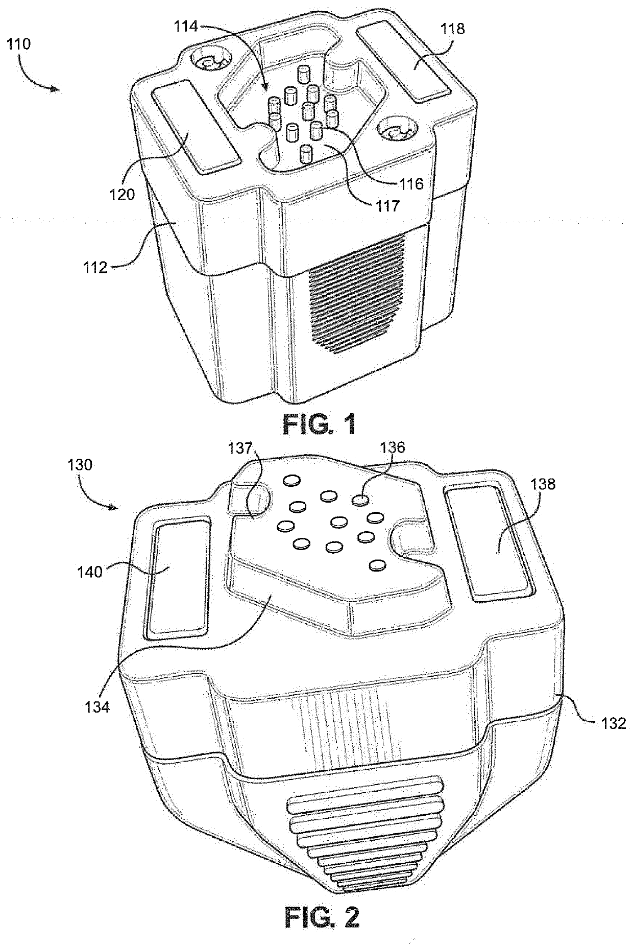
[0037]Referring initially to FIG. 1, a female connector 110 of a preferred embodiment of a Magnetic Connector Assembly 100 has a body 112 with a cavity 114 defining an indentation into the body 112. In a preferred embodiment, cavity 114 has a rotationally symmetrical but otherwise irregular shape. In a preferred embodiment, the rotational symmetry is two-fold, meaning that the shape of cavity 114 is the same (in that it does not appear to have a distinct orientation) when rotated one-hundred eighty (180) degrees. A plurality of conductive contact pins 116 are on the bottom surface 117, outward-facing surface of cavity 114. In a preferred embodiment, contact pins 116 are spring-biased and protrude slightly beyond the bottom surface 117 of cavity 114, but remaining fully within the cavity 114 itself. Magnets 118 and 120 are situated outside of and on opposite ends of the cavity 114 of body 112.

[0038]Referring now to FIG. 2, a male connector 130 corresponding to female connector 110 is...


PUM


Abstract

A magnetic connector assembly has a female connector with spring-loaded conductive pins slightly protruding inside a recess or cavity in the female connector's body. A corresponding male connector has a protrusion on its body with conductive pins slightly indented into the protrusion's surface. The protrusion on the male connector is sized and shaped to fit into the cavity in the female connector such that the male connector's pins engage the pins of the female connector, allowing for electrical communication across the connector assembly. Magnets on the male and female connectors secure them in a correct orientation. A unique shape ensures proper alignment of the pins and prevents the connection of incompatible devices.

Description

RELATED APPLICATIONS[0001]This application claims the benefit of priority to U.S. Provisional Patent Application Ser. No. 62 / 801,910 titled Magnetic Connector Assembly filed Feb. 6, 2019, and currently co-pending, and the entirety of which is incorporated fully herein by this reference.FIELD OF THE INVENTION[0002]The present invention pertains generally to connectors for use in electronic devices and data communication. More particularly, the present invention pertains to self-aligning, magnetically biased connectors. The Present invention is particularly, but not exclusively, useful as a self-aligning connector for connecting signal carriers.BACKGROUND OF THE INVENTION[0003]It is generally known to provide magnetic coupling elements in electrical and non-electrical connectors. Examples of connectors that include magnetic coupling elements are disclosed in U.S. Pat. Nos. 4,484,761; 4,776,406; 7,277,013 and 7,334,433. Examples of magnetic breakaway connection devices for power lines ...

Claims


Application Information

Patent Timeline
Patent Type & Authority Applications(United States)
IPC IPC(8): H01R13/62H01R13/64
CPCH01R13/64H01R13/6205H01R13/642H01R13/2421H01R13/621H01R13/6456
Inventor LEE, VINCENT
Owner LEE VINCENT
Why Eureka
Try Eureka