
Assist apparatus

a technology of assist force and apparatus, which is applied in the field of assist apparatus, can solve the problems of difficulty in responding to physical variations, and difficulty in reducing the operator's burden, so as to reduce the risk of injuring the back, reduce the risk of lifting work, and reduce the burden

Inactive Publication Date: 2020-09-17
JTEKT CORP
View PDF0 Cites 8 Cited by
  • Summary
  • Abstract
  • Description
  • Claims
  • Application Information

AI Technical Summary

Benefits of technology

The wearable boost apparatus described in this patent is designed to enable efficient lifting of heavy loads while reducing injury risks to the back. It includes a boost transmission mechanism and a reaction force reception mechanism. The apparatus is lightweight, can adjust to different physical sizes, and high-capacity to follow wearer movement. During walking, it allows easy walking without adding assist force. The apparatus is convenient to use with a length adjustment device based on the wearer's physical size. The use of different cables and guides ensures proper power transmission and efficient movement.

Problems solved by technology

As stated above, in the wearable boost apparatus described in JP 2003-265548 A, the assist force transmission mechanisms include rigid body components such as various types of rods and thus are poor in capability of following movement of the wearer and are very heavy, causing difficulty in reducing the operator's burden.
Also, because of including rigid body components such as various types of rods, the assist force transmission mechanisms have difficulty in responding to variations in physical size of wearers.
In addition, positions of, e.g., each of joints in the wearable boost apparatus are easily displaced from ideal positions for the wearer, which may cause discomfort in wearing, and in addition, may cause a decrease in assist force transmission efficiency.
Furthermore, when the wearer travels to a work site at which the wearer performs the work of, e.g., lifting and lowering packages, on foot, if no assist force is generated, the wearer cannot easily walk because of resistance of the actuator being imposed.

Method used


Image

  • Assist apparatus
  • Assist apparatus
  • Assist apparatus

Examples


Embodiment Construction

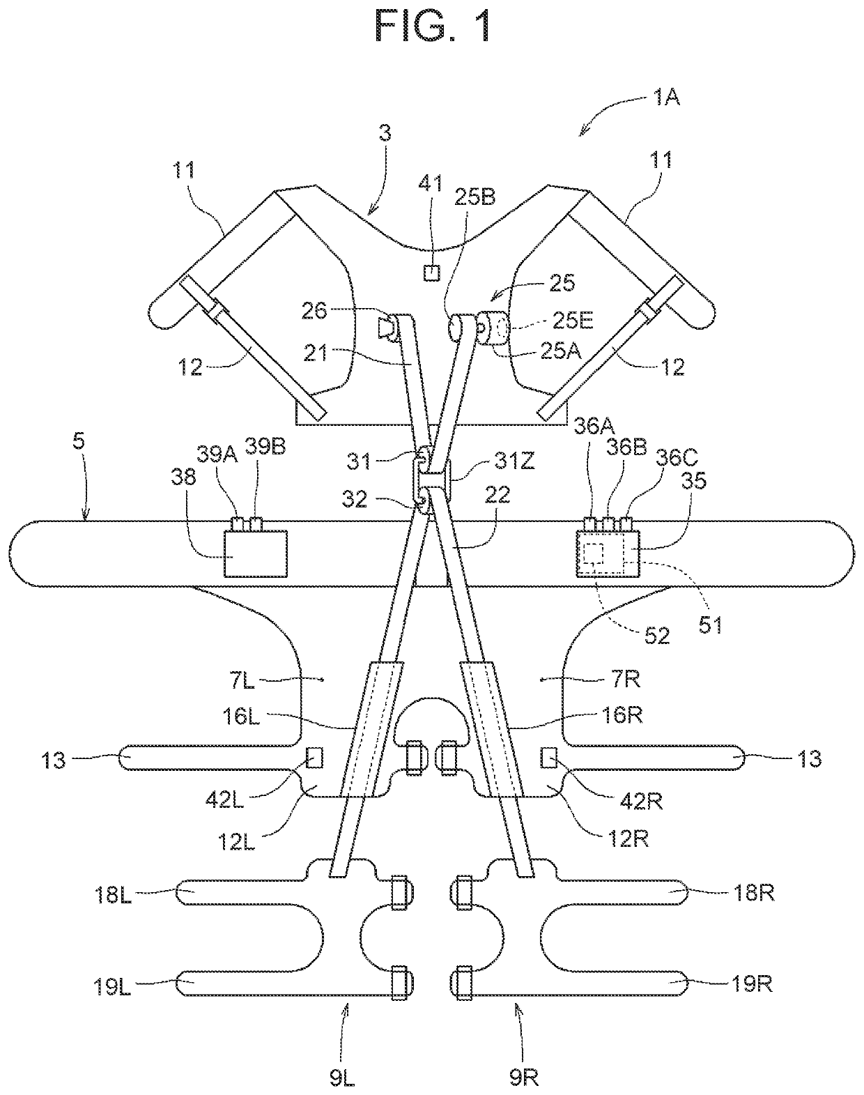
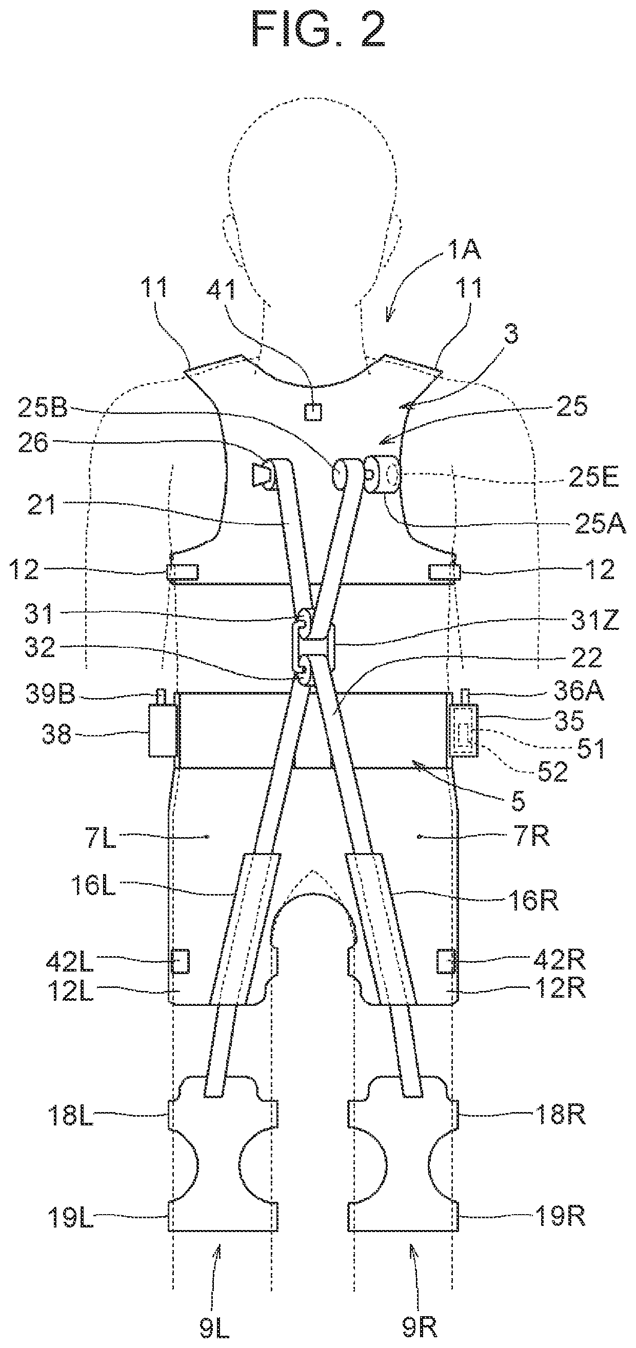
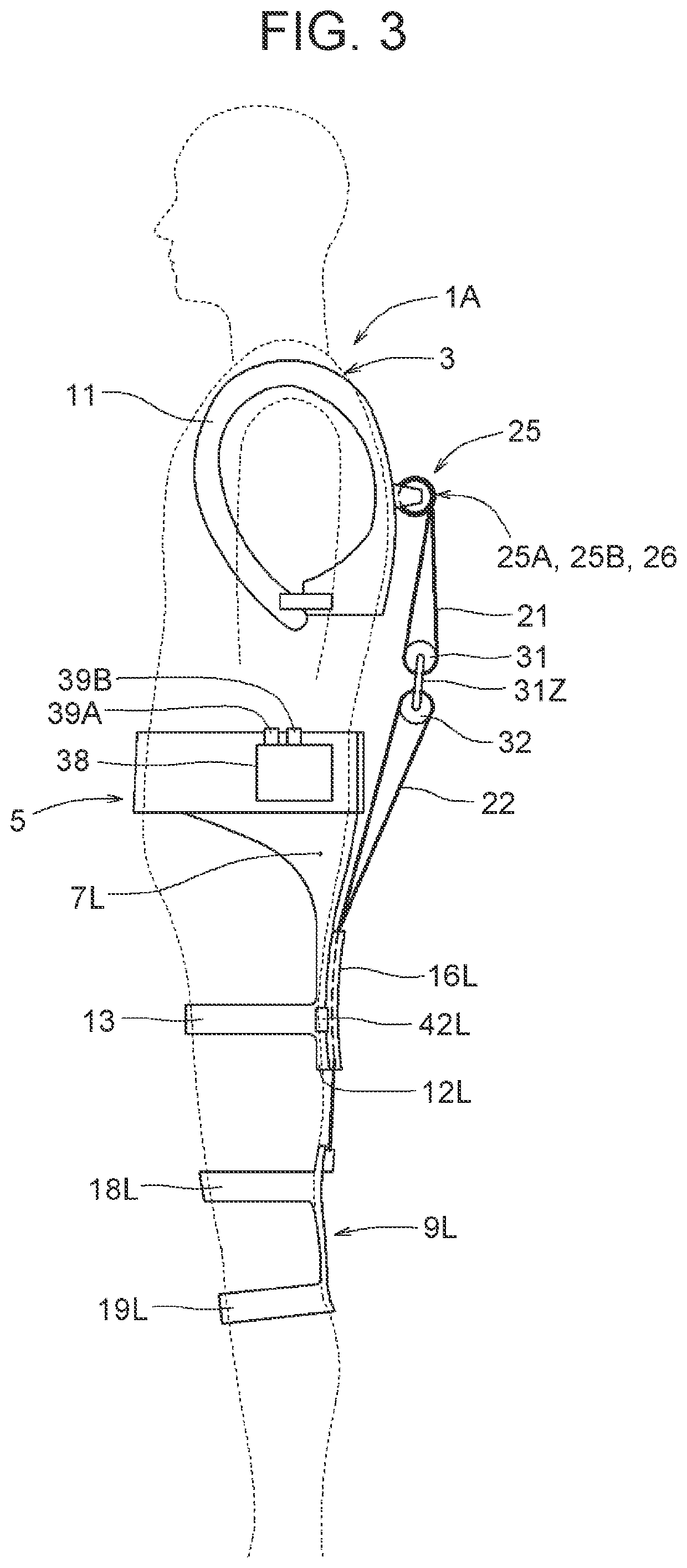
[0034]First to fourth embodiments, each of which is an embodiment of an assist apparatus according to the present disclosure, will be described in detail below with reference to the drawings. First, a schematic configuration of an assist apparatus 1A according to a first embodiment will be described based on FIGS. 1 to 5.

[0035]As illustrated in FIGS. 1 to 4, an assist apparatus 1A includes, e.g., a shoulder harness 3 to be fitted to the upper back region and right and left shoulder regions of a wearer, a belt-like waist harness 5 to be fitted to the waist region of the wearer, a right hip harness 7R to be fitted to the right hip region of the wearer, a left hip harness 7L to be fitted to the left hip region of the wearer, a right knee harness 9R to be fitted to the right knee region, including a region below the right knee, of the wearer and a left knee harness 9L to be fitted to the left knee region, including a region below the left knee, of the wearer. The shoulder harness 3, the...


PUM


Abstract

An assist apparatus includes: a shoulder harness; an actuator; a power transmission member connected to the actuator; a pulley support portion; a leg-side pulley; a knees-linking member; a left knee harness to be fitted to a left knee region of the wearer, the left knee harness being connected to a first end of the knees-linking member; a right knee harness to be fitted to a right knee region of the wearer, the right knee harness being connected to a second end of the knees-linking member; a posture detection device that detects a posture of the wearer; and a control device that controls the actuator based on information of the posture of the wearer, the posture being detected by the posture detection device.

Description

CROSS-REFERENCE TO RELATED APPLICATIONS[0001]This application claims priority to Japanese Patent Application No. 2019-043462 filed on Mar. 11, 2019, Japanese Patent Application No. 2019-043463 filed on Mar. 11, 2019, and Japanese Patent Application No. 2019-043464 filed on Mar. 11, 2019, each incorporated herein by reference in its entirety.BACKGROUND1. Technical Field[0002]The present disclosure relates to an assist apparatus that assists work in a state of being worn on a human body.2. Description of Related Art[0003]Various assist apparatuses that assist work in a state of being worn on a human body have been proposed. For example, Japanese Patent Application Publication No. 2003-265548 (JP 2003-265548 A) describes a wearable boost apparatus including a wire wind-up drum, which serves as a drive section, in a drive section fitting mechanism to be detachably fitted to the hip region of a user. A boost transmission mechanism to be detachably fitted to the upper part of the user's b...

Claims


Application Information

Patent Timeline
IPC IPC(8): A61H3/00A61H1/02
CPCA61H2201/1628A61H2201/164A61H3/00A61H2201/1207A61H2201/1671A61H2003/007A61H2201/5064A61H2205/102A61H1/0281A61H2201/1652B25J9/0006A61H1/00
Inventor SATO, HISATAKAARAI, TOMOKITAKEUCHI, SHINJI
Owner JTEKT CORP
Learn More