Transformer, power supply, and medical system

Active Publication Date: 2020-09-17
TDK CORPARATION
View PDF2 Cites 4 Cited by
  • Summary
  • Abstract
  • Description
  • Claims
  • Application Information

AI Technical Summary

Benefits of technology

The present invention aims to provide a transformer that can efficiently dissipate heat and maintain a constant distance between the primary and secondary windings. It is useful for power supplies and medical systems. The invention allows for more efficient heat transfer to the magnetic core while keeping the windings separate. The medical system with this power supply meets medical standards while achieving the effects of the power supply alone.

Problems solved by technology

However, when a lot of heat is generated in the primary winding and the secondary winding, a configuration that merely separates the primary winding and the secondary winding will not sufficiently dissipate the heat, resulting in the problem of a large rise in the temperature of the primary winding and the secondary winding.

Method used


Image

  • Transformer, power supply, and medical system
  • Transformer, power supply, and medical system
  • Transformer, power supply, and medical system

Examples


Embodiment Construction

[0036]Preferred embodiments of a transformer, a power supply, and a medical system will now be described with reference to the attached drawings.

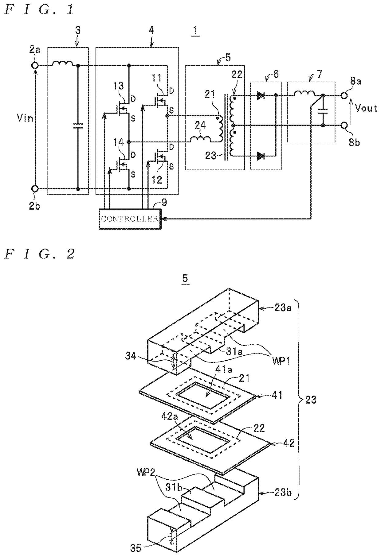
[0037]First, the configuration of a power supply 1 as one example of a “power supply” according to the present invention and the configuration of a transformer 5 as one example of a “transformer” according to the present invention will be described together while referring to the drawings. As one example, as depicted in FIG. 1, the power supply 1 includes a pair of input terminals 2a and 2b (hereinafter referred to as the “input terminals 2” when no particular distinction is made between them) , a primary-side smoothing circuit 3, a switch 4, the transformer 5, a rectifier 6, a secondary-side smoothing circuit 7, and a pair of output terminals 8a and 8b (hereinafter referred to as the “output terminals 8” when no particular distinction is made between them). The power supply 1 generates a direct current (DC) output voltage Vout based on a D...


PUM


Abstract

A transformer includes a primary winding and a secondary winding, which are flat, and a magnetic core that has a middle leg that passes through the primary and secondary windings, a first core that is connected to one end along the length direction of the middle leg, and a second core that is connected to the other end along the length direction. A first wall surface on the side of the first core where the middle leg is positioned and a second wall surface on the side of the second core which faces the first wall surface are formed so as to be parallel, the primary winding is fixed to the first wall surface, the secondary winding is fixed to the second wall surface, and the distance between the primary winding and the secondary winding is kept constant.

Description

FIELD OF THE INVENTION[0001]The present invention relates to a transformer equipped with a primary winding, a secondary winding, and a core, to a power supply equipped with such transformer, and to a medical system equipped with such power supply.DESCRIPTION OF THE RELATED ART[0002]As one example of a transformer of this type, the transformer used in the power supply (an isolation switching power supply) disclosed in Patent Literature 1 (Japanese Laid-open Patent Publication No. 2016-165176) is known. This transformer includes: a first circuit board on which a primary winding that constructs an isolation transformer is formed as a pattern; a second circuit board on which a secondary winding that constructs the isolation transformer is formed as a pattern and is disposed so that the part where the secondary winding is formed faces the part of the first circuit board where the primary winding is formed with a predetermined gap in between; a core that is inserted through the primary wi...

Claims


Application Information

Patent Timeline
IPC IPC(8): H01F27/28H02M3/335H01F30/06H05K1/02
CPCH02M3/33592H01F30/06H01F2027/2819H05K1/0233H01F27/2804H01F27/2876H01F27/306H02M3/33573H02M3/01H01F27/22H01F27/06H01F2027/065Y02B70/10H05K1/165H05K1/144H05K2201/086H05K2201/09063H02M1/0058H02M3/003
Inventor ISHIZAWA, KAZUKITAKAYAMA, KENONO, MASAYOSHIHIURA, JYUNYA
Owner TDK CORPARATION
Why Eureka
Try Eureka