Electronically commutated axial conductor motor

a conductor motor and electric commutation technology, applied in the direction of control/drive circuits, dynamo-electric machines, supports/enclosements/casings, etc., can solve the problems of complex and expensive robotics, no reduction in manufacturing costs, and no significant improvement in motor performance. , to achieve the effect of saving labor costs

Active Publication Date: 2020-09-17
HENDRICKS ROBERT C
View PDF8 Cites 6 Cited by
  • Summary
  • Abstract
  • Description
  • Claims
  • Application Information

AI Technical Summary

Benefits of technology

[0025]The motor of the invention also lends itself to automated production; the end-rings may be produced using integrated circuit fabrication techniques, and the conductors inserted into the sta

Problems solved by technology

To date, the problem of automating these windings has not been solved and at best is likely to require complex and expensive robotics, yielding neither a reduction in manufacturing cost nor significant improvement in motor performance.
Furthermore,

Method used


Image

  • Electronically commutated axial conductor motor
  • Electronically commutated axial conductor motor
  • Electronically commutated axial conductor motor

Examples


Embodiment Construction

[0033]The following description of the preferred embodiment is presented to describe the present invention without limiting the scope of the appended claims in any manner whatsoever.

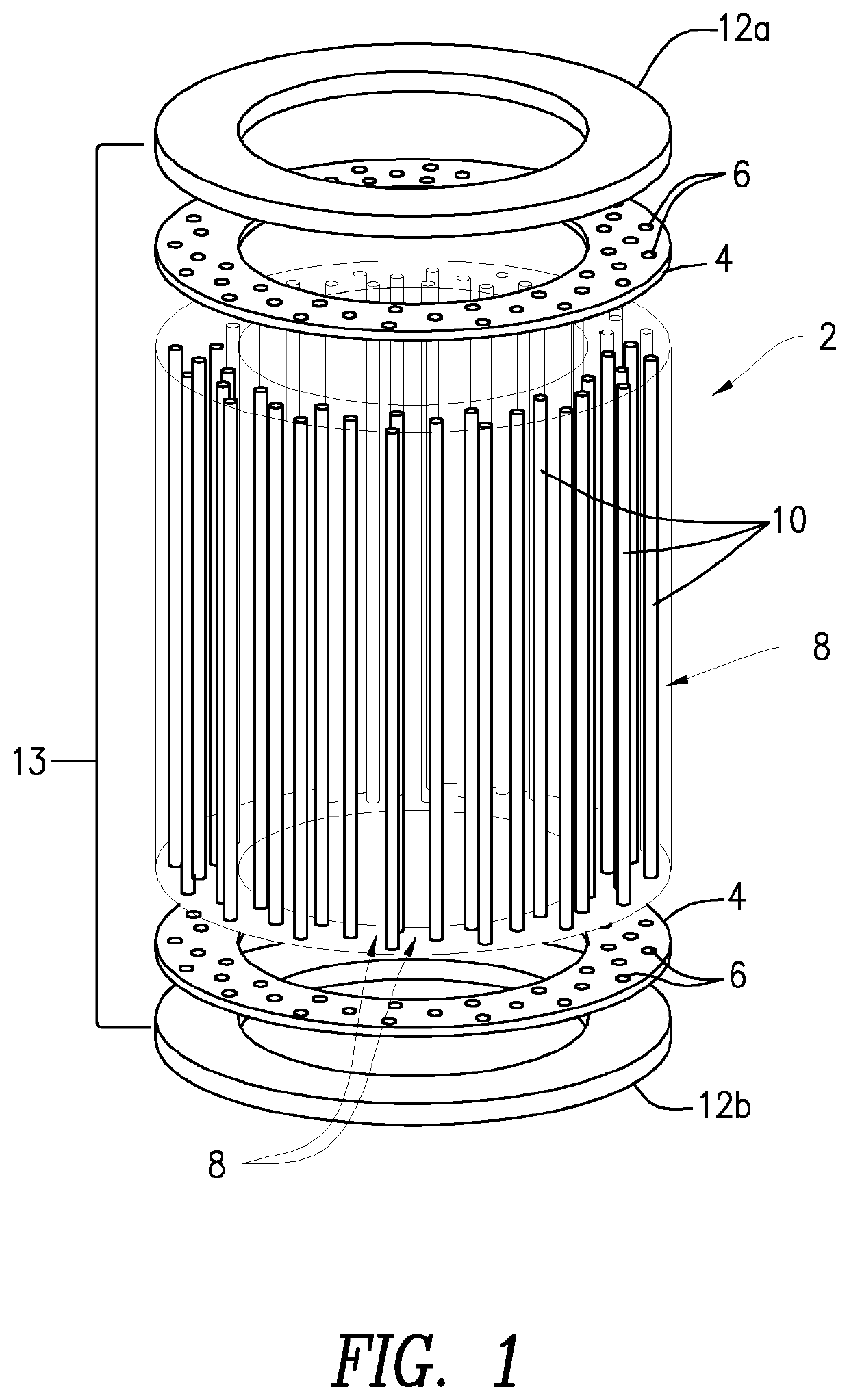
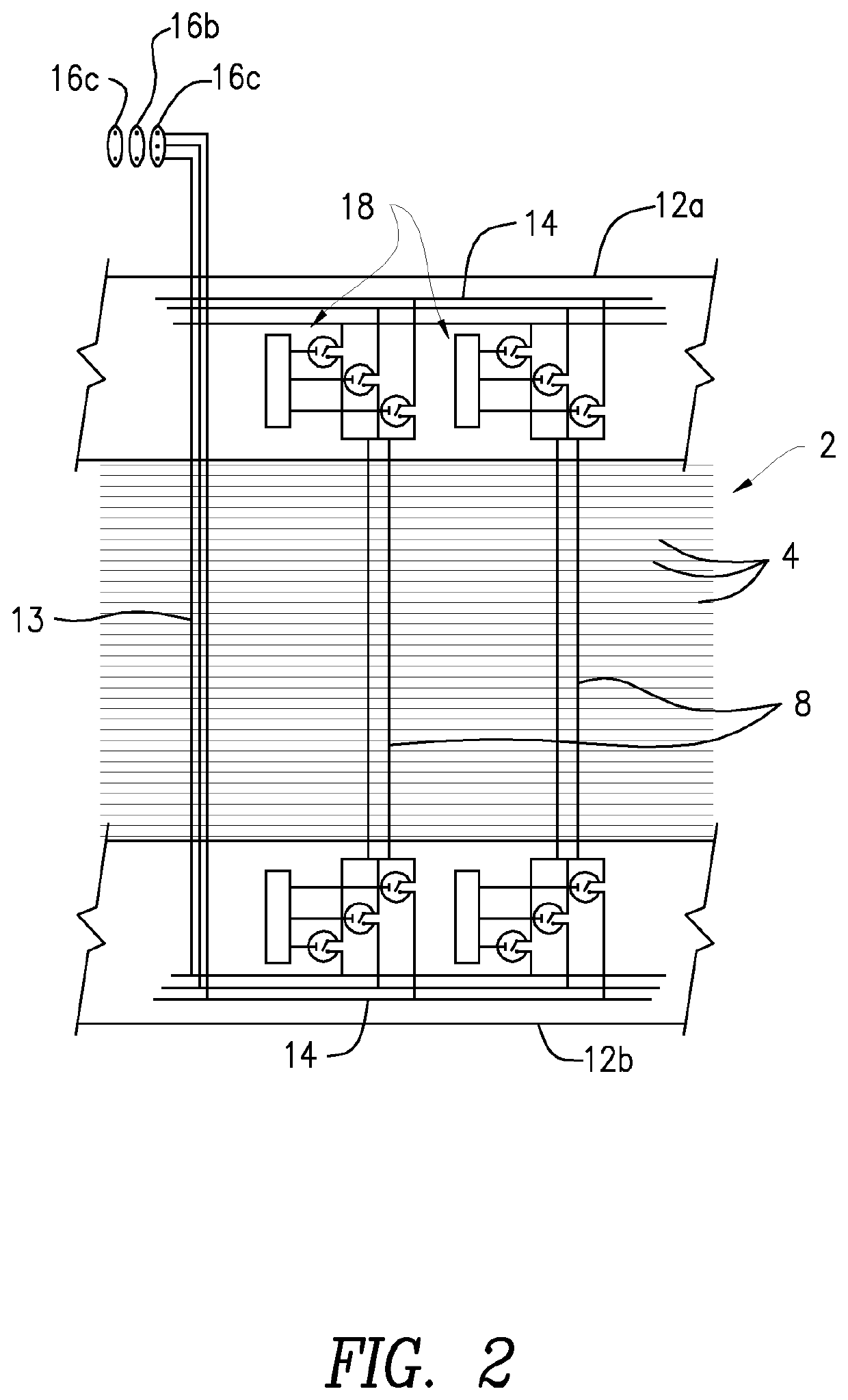
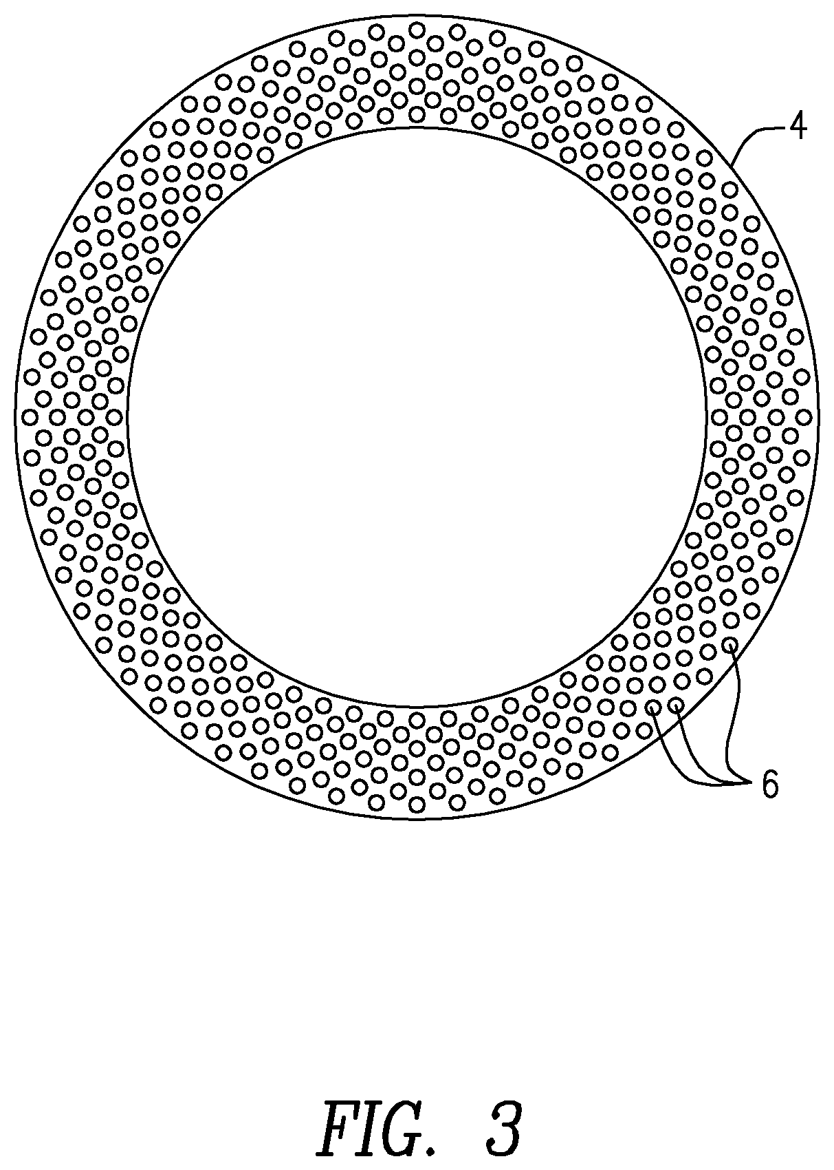
[0034]As shown in FIGS. 1-5, the present claimed invention is directed to an electronic motor comprising a stator assembly or core 2, preferably formed of laminated stack or plate elements 4, having a plurality of holes 6 therein and a plurality of conductors 8 comprising a substantially linear body portion 10 extending within the holes 6 of stator core 2, and a stator drive member 12 adjacent each end of the stator core 4, the stator end member 12 adjacent at least one of the ends of the stator core 4 comprising electronic control circuitry 14.

[0035]A power jumper 13 provides an electrical connection between upper and lower stator end members 12 having one or more switches 18 coupled to the conductors 8, and to an output connection, shown in FIG. 1 with an optional DC connection 16a, single phase connec...


PUM


Abstract

An electronic motor with a stator core having a plurality of holes for receiving a plurality of conductors, each conductor comprising a substantially linear body portion extending within the holes of the stator core, and a stator drive member adjacent each end of the stator core, the stator end member adjacent at least one end of the stator core including electronic control circuitry electrically coupled to at least some of the conductors.
Also, a method of manufacturing an electronic motor by providing a stator with a plurality of holes having conductors within at least some of the plurality of holes, said conductors each having a substantially linear body portion extending through the stator core, and placing a drive member on each end of the stator core, at least one of the drive members provided with electronic circuitry, where the conductors are electrically coupled to the circuitry in the drive member.

Description

FIELD OF THE INVENTION[0001]The present invention relates to electronic induction motors, and more particularly to an electronically commutated axial conductor motor.BACKGROUND OF THE INVENTION[0002]The three-phase induction motor is the workhorse of industry, and is produced in large quantities all over the world. Regardless of size, the standard design of this type of motor has the common features of a ferrous stator, usually constructed of a laminated stack of punched steel plates, and a set of windings inserted into longitudinal slots distributed radially around the inside circumference of the stator.[0003]To date, the problem of automating these windings has not been solved and at best is likely to require complex and expensive robotics, yielding neither a reduction in manufacturing cost nor significant improvement in motor performance. Therefore the majority of three-phase induction motors are assembled using manual labor, at least for the process of lacing, insulating and ins...

Claims


Application Information

Patent Timeline
IPC IPC(8): H02K11/33H02K5/22
CPCH02K5/225H02K2211/03H02K11/33H02K2213/09H02K2213/12H02K2213/06H02K3/50H02K41/02H02K3/12H02K3/28
Inventor HENDRICKS, ROBERT C.
Owner HENDRICKS ROBERT C
Why Eureka
Try Eureka