Workpiece fixing jig

a technology for fixing jigs and workpieces, which is applied in the direction of positioning apparatuses, metal-working machine components, manufacturing tools, etc., can solve the problems of reducing production efficiency, mounting errors and the time taken for arrangement changes, and requiring multiple processes, so as to improve production efficiency and reduce production costs , the effect of simple configuration

Inactive Publication Date: 2020-09-24
OKUMA CORP
View PDF0 Cites 4 Cited by
  • Summary
  • Abstract
  • Description
  • Claims
  • Application Information

AI Technical Summary

Benefits of technology

[0007]In order to achieve the above-described object, a workpiece fixing jig for fixing a workpiece to a table or a pallet of a machine tool is provided. According to a first aspect of the disclosure, the workpiece fixing jig includes a base plate, a support block, a bolt, and a drop prevention unit. The base plate is clamped or unclamped to the table or the pallet. The support block is disposed upright on the base plate and has a placement surface for the workpiece on a top surface of the support block. The bolt is housed in the support block to be movable up and down and is projected from the placement surface to be screwable into a lower surface of the workpiece. The drop prevention means prevents the bolt from dropping from the inside of the support block.
[0010]According to the first aspect of the disclosure, the bolt is screwed into the lower surface of the workpiece without a risk of dropping to ensure fixing the workpiece. Accordingly, simultaneous multi-surface machining can be performed, and the fixation of the workpiece which leads to improvement in production efficiency can be achieved with a simple configuration at a low cost.
[0011]According to the second aspect of the disclosure, in addition to the effect of the first aspect, the drop prevention means is easily formed, because it includes the stopper plate and the nut.
[0012]According to the third aspect of the disclosure, in addition to the effects of the first aspect and the second aspect, the communication hole is formed to penetrate through the base plate under the bolt and the clamped portion for conveyance is provided on the side surface of the base plate. Therefore, with an industrial robot or the like, fixing the workpiece to the workpiece fixing jig, releasing the fixation, and conveying the workpiece to the table and / or the pallet can be automatically performed, and thus an application to an automatic machining line becomes possible.

Problems solved by technology

However, a plurality of processes are required for a workpiece which has a complicated shape and needs multi-surface machining, since arrangement change, such as a change of a posture of a workpiece and a position of a jig, is required.
The arrangement change leads to a mounting error of the workpiece or an extra time for arrangement change, which causes lowering production efficiency.
Therefore, simultaneous multi-surface machining can be performed, and the mounting error and the time taken for arrangement change decrease.
However, the use of the magnetic fixing device causes increasing of a size of the device and its weight, resulting in a rise in cost.

Method used


Image

  • Workpiece fixing jig
  • Workpiece fixing jig
  • Workpiece fixing jig

Examples


Embodiment Construction

[0025]The following describes embodiments of the disclosure based on the drawings.

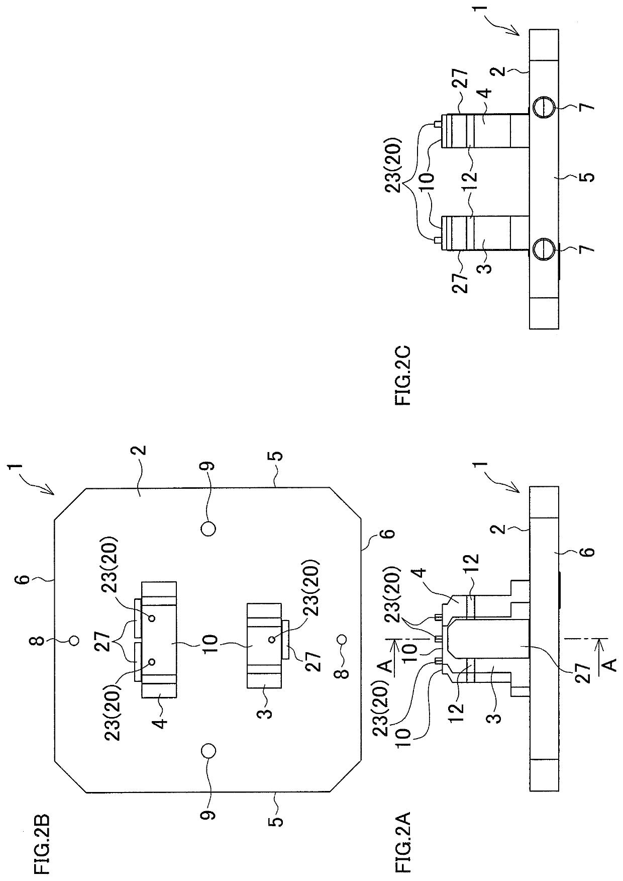
[0026]FIG. 1 is a perspective view illustrating one example of a workpiece fixing jig. FIG. 2A to FIG. 2C are respective explanatory views of the workpiece fixing jig. FIG. 2A illustrates a front surface, FIG. 2B illustrates a planar surface, and FIG. 2C illustrates a side surface.

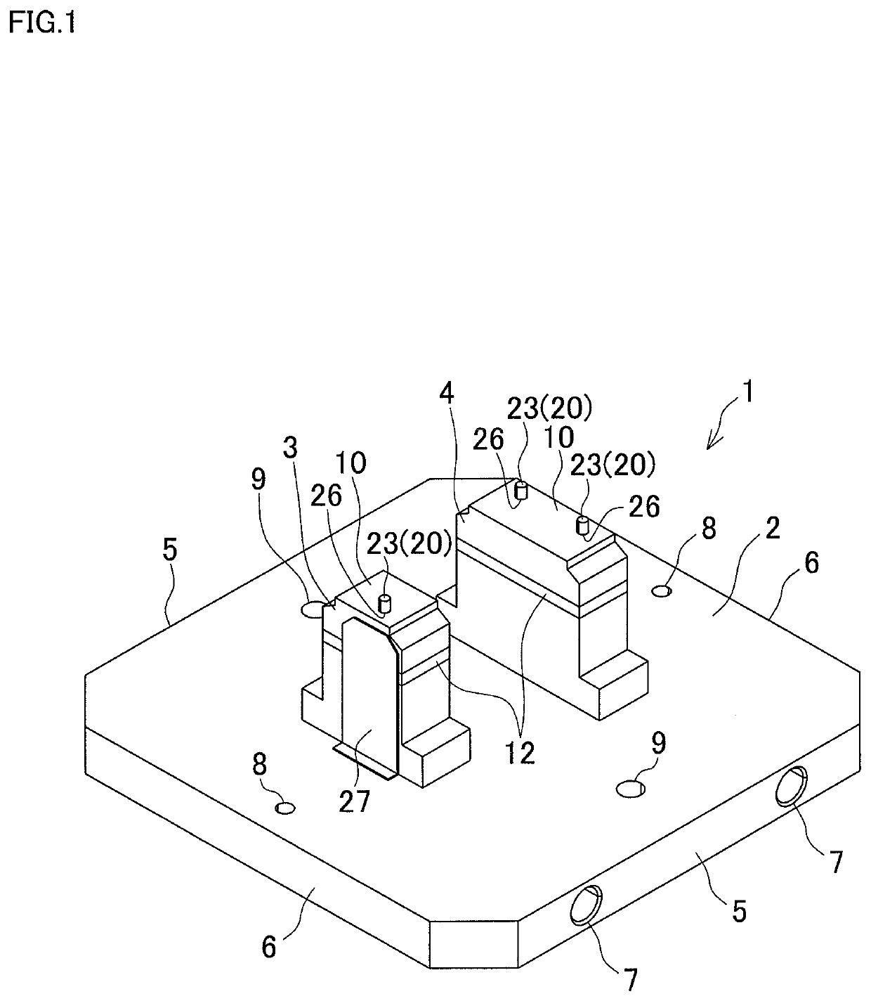
[0027]A workpiece fixing jig 1 includes a base plate 2 and two supports blocks, which are a first support block 3 and a second support block 4, fixed to a top surface of the base plate 2.

[0028]The base plate 2 has a square shape in plan view whose corner portions are chamfered and includes a pair of parallel first side surfaces 5, 5, and a pair of parallel second side surfaces 6, 6 perpendicular to the first side surfaces 5, 5. A pair of conveyance holes 7, 7 are formed in the respective first side surfaces 5, 5. Additionally, a pair of temporary placement holes 8, 8 are each formed to penetrate in an up-down direction in edg...


PUM


Abstract

A workpiece fixing jig for fixing a workpiece to a table and / or a pallet of a machine tool includes a base plate, a support block, a bolt, and a drop prevention unit. The base plate is clamped or unclamped to the table and / or the pallet. The support block is disposed upright on the base plate. The support block has a placement surface for the workpiece on a top surface of the support block. The bolt is housed in the support block to be movable up and down. The bolt is projected from the placement surface to be screwable into a lower surface of the workpiece. The drop prevention unit prevents a drop of the bolt from the inside of the support block.

Description

BACKGROUND OF THE INVENTION[0001]This application claims the benefit of the Japanese Patent Application Number 2019-051533 filed on Mar. 19, 2019, the entirety of which is incorporated by reference.FIELD OF THE INVENTION[0002]The disclosure relates to a workpiece fixing jig used to fix a workpiece on a table and / or a pallet of a machine tool.RELATED ART[0003]To process a workpiece by a machine tool, the workpiece is fixed on a pallet and / or a table using a jig, such as an angle plate. For example, JP-A-2006-142419 discloses a mounting auxiliary base where a mounting tool body to which a workpiece is mounted using a fastening member, such as a damper, is coupled to a base body via a plurality of positioning members and the base body is configured to be mounted to a pallet with bolts.[0004]However, a plurality of processes are required for a workpiece which has a complicated shape and needs multi-surface machining, since arrangement change, such as a change of a posture of a workpiece...

Claims


Application Information

Patent Timeline
Patent Type & Authority Applications(United States)
IPC IPC(8): B23Q1/03
CPCB23Q1/03B23Q3/06
Inventor IDO, TOMOMI
Owner OKUMA CORP
Why Eureka
Try Eureka