Driving method for display panel

Active Publication Date: 2020-09-24
WUHAN CHINA STAR OPTOELECTRONICS TECH CO LTD
View PDF0 Cites 0 Cited by
  • Summary
  • Abstract
  • Description
  • Claims
  • Application Information

AI Technical Summary

Benefits of technology

[0029]Beneficial effects of the present disclosure is that the present disclosure provides an driving method for a display panel, through making the first demultiplexing signal, the second demultiplexing signal, the third demultiplexing signal, the fourth demultiplexing signal, the fifth demultiplexing signal and the sixth demultiplexing signal according to the first sequence generate the high-level pulse in the first image frame, and through making the first

Problems solved by technology

However, with improvement of resolution of a liquid crystal display panel, the number of data lines and gate lines also increases, a

Method used


Image

  • Driving method for display panel
  • Driving method for display panel
  • Driving method for display panel

Examples


first embodiment

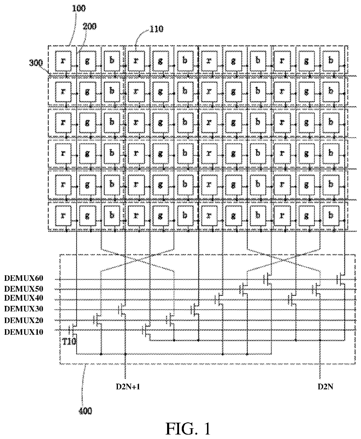
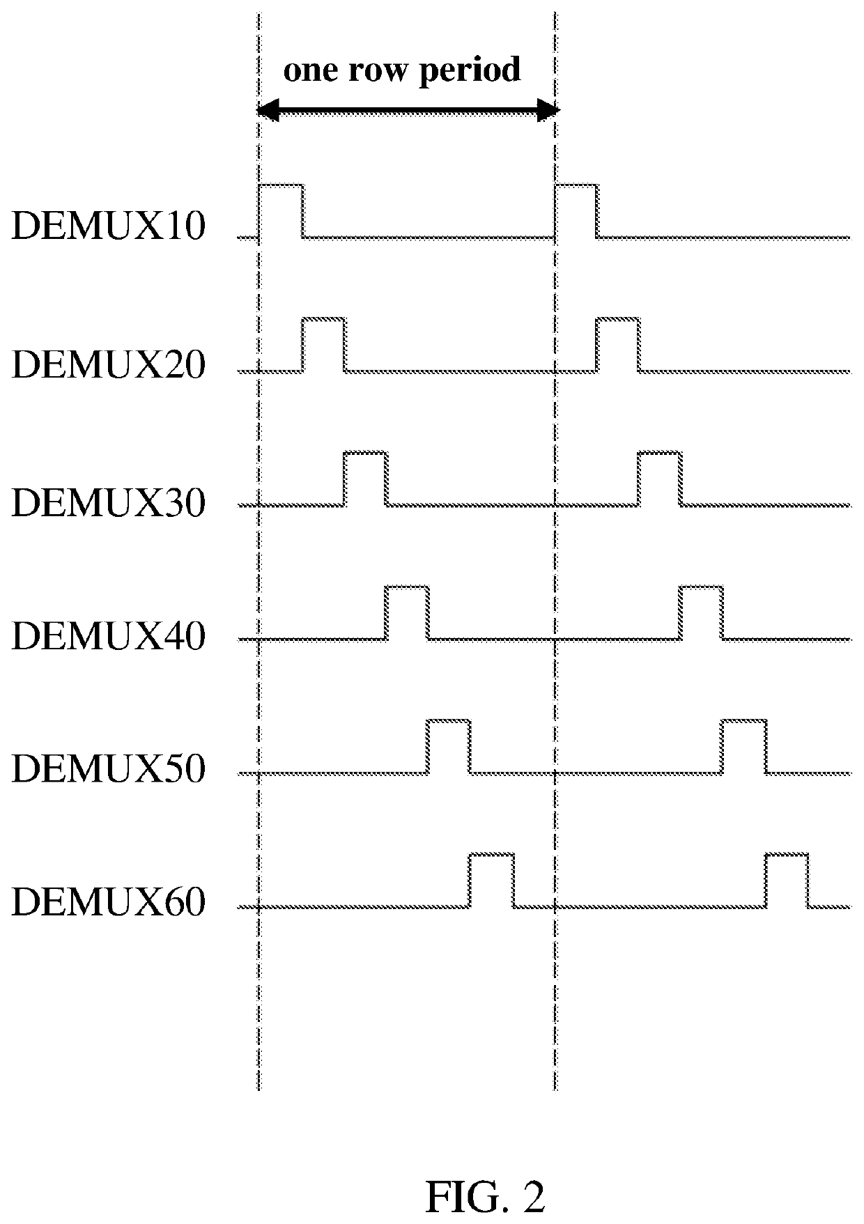
[0056]Optionally, as illustrated in FIG. 6 and FIG. 7, in the present disclosure, the first sequence is: in the first image frame, during scanning each row of the subpixels, sequentially generating the high-level pulse according to a sequence of the first demultiplexing signal DEMUX1, the second demultiplexing signal DEMUX2, the third demultiplexing signal DEMUX3, the fourth demultiplexing signal DEMUX4, the fifth demultiplexing signal DEMUX5 and the sixth demultiplexing signal DEMUX6; the second sequence is: in the second image frame, during scanning each row of the subpixels, sequentially generating the high-level pulse according to a sequence of the sixth demultiplexing signal DEMUX6, the fifth demultiplexing signal DEMUX5, the fourth demultiplexing signal DEMUX4, the third demultiplexing signal DEMUX3, the second demultiplexing signal DEMUX2 and the first demultiplexing signal DEMUX1.

[0057]It should be noted, that in the first embodiment of the present disclosure, in the first i...

third embodiment

[0060]Optionally, as illustrated in FIG. 10 and FIG. 11, in the present disclosure, the first sequence is: in the first image frame, when scanning the 4i-3th row subpixels and the 4i-2th row subpixels, sequentially generating the high-level pulse according to a sequence of the first demultiplexing signal DEMUX1, the second demultiplexing signal DEMUX2, the third demultiplexing signal DEMUX3, the fourth demultiplexing signal DEMUX4, the fifth demultiplexing signal DEMUX5 and the sixth demultiplexing signal DEMUX6; during scanning the 4i-1th row subpixels and the 4ith row subpixels, sequentially generating the high-level pulse according to a sequence of the sixth demultiplexing signal DEMUX6, the fifth demultiplexing signal DEMUX5, the fourth demultiplexing signal DEMUX4, the third demultiplexing signal DEMUX3, the second demultiplexing signal DEMUX2 and the first demultiplexing signal DEMUX1.

[0061]The second sequence is: in the second image frame, during scanning the 4i-3th row subpi...

fourth embodiment

[0063]Optionally, as illustrated in FIG. 12 and FIG. 13, as illustrated in the present disclosure, the first sequence is: in the first image frame, during scanning each row of the subpixels, sequentially generating the high-level pulse according to a sequence of the first demultiplexing signal DEMUX1, the second demultiplexing signal DEMUX2, the third demultiplexing signal DEMUX3, the fourth demultiplexing signal DEMUX4, the fifth demultiplexing signal DEMUX5 and the sixth demultiplexing signal DEMUX6.

[0064]The second sequence is: in the second image frame, during scanning each row of the subpixels, sequentially generating the high-level pulse according to a sequence of the fourth demultiplexing signal DEMUX4, the fifth demultiplexing signal DEMUX5, the sixth demultiplexing signal DEMUX6, the first demultiplexing signal DEMUX1, the second demultiplexing signal DEMUX2 and the third demultiplexing signal DEMUX3.

[0065]It should be noted, that in the fourth embodiment, through adding th...


PUM


Abstract

A driving method for a display panel is through making the first demultiplexing signal, the second demultiplexing signal, the third demultiplexing signal, the fourth demultiplexing signal, the fifth demultiplexing signal and the sixth demultiplexing signal according to the first sequence generate the high-level pulse in the first image frame, and through making the first demultiplexing signal, the second demultiplexing signal, the third demultiplexing signal, the fourth demultiplexing signal, the fifth demultiplexing signal and the sixth demultiplexing signal according to the second sequence different from the first sequence generate the high-level pulse in the second image frame, thereby by adding the effect of the two image frames to eliminate stripes on the images displayed by the display panel to improve the display effect.

Description

FIELD OF INVENTION[0001]The present disclosure relates to a display technology field, and particular to a driving method for the display panel.BACKGROUND OF INVENTION[0002]With development of display technology, because liquid crystal displays (LCDs) and such flat-panel display devices have advantages of high picture quality, power savings, thin bodies and wide application range, having gradually replaced cathode ray tube (CRT) display screen and being widely applied in mobile phones, televisions, personal digital assistants, laptops, desktop computers and such consumer electronics, having be the mainstream display devices.[0003]Most LCDs in the current market are backlight LCDs, which include a liquid crystal display panel and a backlight module. The working principle of a liquid crystal display panel is to dispose liquid crystal molecules between a thin film transistor (TFT) array substrate and a color filter (CF) substrate, and applying a driving voltage between the two substrate...

Claims


Application Information

Patent Timeline
IPC IPC(8): G09G3/20
CPCG09G2310/0202G09G2320/0233G09G2310/0297G09G2300/0809G09G3/20G09G3/3648G09G2320/0204
Inventor ZHENG, LIHUAZHAO, MANG
Owner WUHAN CHINA STAR OPTOELECTRONICS TECH CO LTD
Why Eureka
Try Eureka