Device and method for the production of plastic parts, more particularly of adhesive applications

a technology for plastic parts and adhesives, applied in the direction of transportation and packaging, mixing, coatings, etc., can solve the problems of affecting the use of components below the mixing head, and affecting the cooling effect of the mixing head. , to achieve the effect of reducing air flow and increasing cooling

Pending Publication Date: 2020-10-01
HENKEL KGAA
View PDF1 Cites 11 Cited by
  • Summary
  • Abstract
  • Description
  • Claims
  • Application Information

AI Technical Summary

Benefits of technology

[0028]In summary, it can be stated that the drying is achieved by a separating device enclosing the mixing device in order to generate a relatively dry atmosphere. In particular, the mixing head is covered by a kind of upside-down dome in the cooled region. Said dome does not have to be particularly close fitting or extremely tight (condensation is not collected by the dome). A very small stream of dried compressed air (said air can also be dried air without high pressure, which

Problems solved by technology

However, these very high reaction speeds cause the reaction process of the two components to progress to a certain point as soon as said components are mixed in the mixing head.
This, in turn, quickly leads to contamination and adhesions in the mixing chamber of the mixing head.
In addition, waiting times between the doses, owing to the process, can also lead to contamination.
The minimum achievable mixing head temperature or mixing chamber temperature is mainly limited by the undesirable formation of condensation.
Since water can be the driving component in the polyurethane foam reaction, even a single drop can make the component below the mixing head unusable.
In many re

Method used


Image

  • Device and method for the production of plastic parts, more particularly of adhesive applications
  • Device and method for the production of plastic parts, more particularly of adhesive applications
  • Device and method for the production of plastic parts, more particularly of adhesive applications

Examples


Embodiment Construction

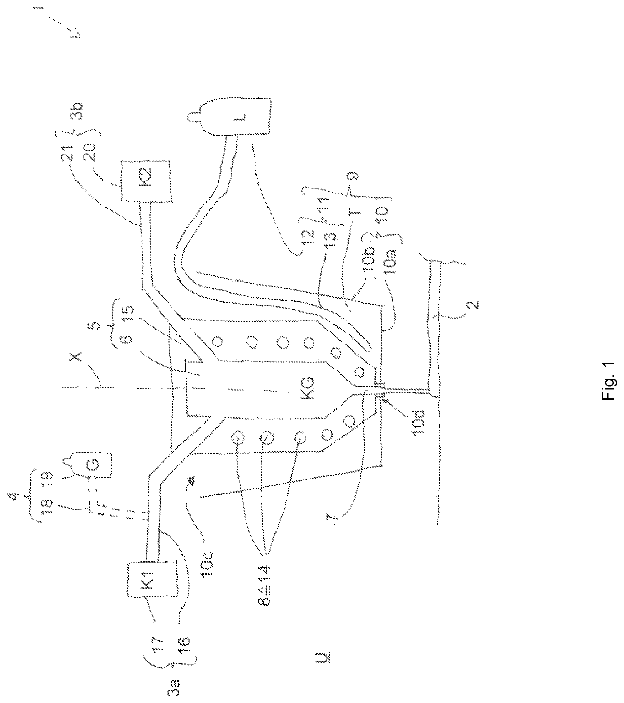
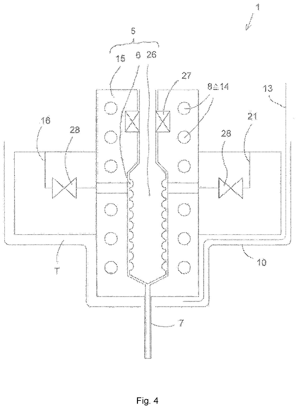
[0034]In FIG. 1, a device 1 for producing plastics parts 2 is shown in a schematic cross section. Specifically, the foamed plastics part 2 in this case is a sealing bead. The device 1 has the mixing device 5 as an essential component. The mixing device 5 has a, preferably metal, housing 15 in which a mixing chamber 6 is formed. A cooling duct 14 of the cooling device 8 is formed in the housing 15 of said mixing device 5. In the illustrated embodiment, the cooling duct 14 is helical (spiraled) around the longitudinal axis X. The cooling duct 14 can also be undulating. The cooling duct 14 is connected to a coolant source (not shown). A cooling liquid such as cooling water, oil, glycol-water mixture, alcohol or the like can be used as the coolant. A line 16 of the first plastics feed device 3a opens into the mixing chamber 6. The first plastics feed device 3a is connected to a source 17 for a first liquid plastics starting component K1. Gas G from a gas source 19 can be fed into the fi...


PUM

PropertyMeasurementUnit
Timeaaaaaaaaaa
Dew pointaaaaaaaaaa

Abstract

The invention relates to a device (1) and method for the production of plastic parts (2), having a first plastic feed device (3a) for feeding a first liquid plastic starting component (K1); a second plastic feed device (3b) for feeding a second liquid plastic starting component (K2); a mixing device (5) with a mixing chamber (6), wherein in the mixing chamber the liquid plastic starting components that can be fed by the plastic feed devices can be mixed to form a plastic mixture (KG); a discharge nozzle (7) for discharging the plastic mixture; and a cooling device (8) for the mixing device, wherein a drying device (9) surrounding the mixing device at least in regions is provided, wherein the drying device has a separating device (10), a drying chamber (T) formed between the separating device and the mixing device, and a desiccant feeding device (11) opening into the drying chamber.

Description

FIELD OF THE INVENTION[0001]The present invention relates to a device for producing plastics parts, in particular adhesive applications, sealing beads, casting parts or the like, comprising a first plastics feed device for feeding a first liquid plastics starting component, a second plastics feed device for feeding a second liquid plastics starting component, a mixing device having a mixing chamber, the liquid plastics starting components which can be fed by the plastics feed devices being mixable in the mixing chamber to form a plastics mixture, a discharge nozzle for discharging the plastics mixture and a cooling device for the mixing device. The invention also relates to a method for operating such a device, comprising the steps of feeding a first liquid plastics starting component and a second liquid plastics starting component to a mixing chamber of a mixing device, mixing the liquid plastics starting components in the mixing chamber to form a plastics mixture, cooling the mixi...

Claims


Application Information

Patent Timeline
IPC IPC(8): B29B7/82B29B7/24B29B7/26B29B7/74
CPCB29B7/7457B29B7/26B29B7/24B29B7/826B29B7/7409B29K2075/00B29B7/22B29B7/58B29B7/80B29B7/82B29B7/823B01F35/00B05C5/0212B05C11/1036B29B7/407B29B7/603B29B7/7414B29B7/845B05C5/001B05C5/0208B29B7/34B29B7/582B29B7/7404B29B7/7636B29B7/7652B29B7/84B29C44/3442B29C44/36B01F35/71B01F35/71805B01F35/7547B01F2035/98B01F35/93B01F2101/2805B01F2101/36B01F33/8364
Inventor METZLER, MARIO
Owner HENKEL KGAA
Why Eureka
Try Eureka